Interfacing ANSYS and LS-DYNA
Sample Problem #8: Impact on a Cylindrical Shell
Pre-Processing
Open ANSYS
· ANSYS Interface has pull-down menu on the top. These menus cover functions such as plotting, display, and selection of entities. Help menu is also at this location.
· ASNSY has also menus on the left side of the screen. These menus cover pre-processing, processing, and post-processing.
· ANSYS needs to know that you are planning to create LS-DYNA model. That is why you need to select LS-DYNA Explicit in the Preferences
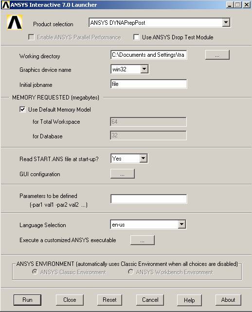
In Windows, select Start
Programs
ANSYS Release 7.0
ANSYS Interactive
In Product Selection, choose: ANSYS DYNAPrepPost
Run

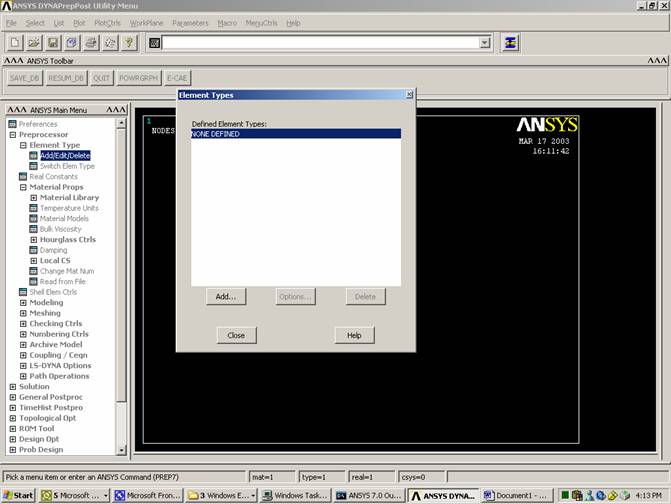
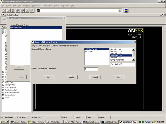
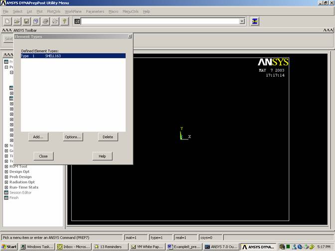
Define element type
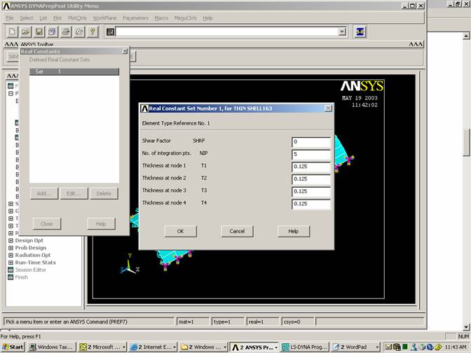
Element Group #1: shell element (thickness=0.125),
Assign Thickness to
the Plates
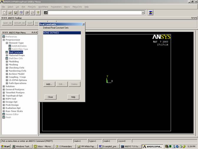
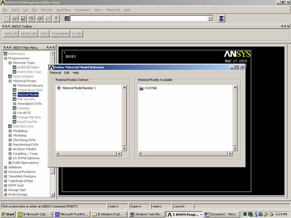
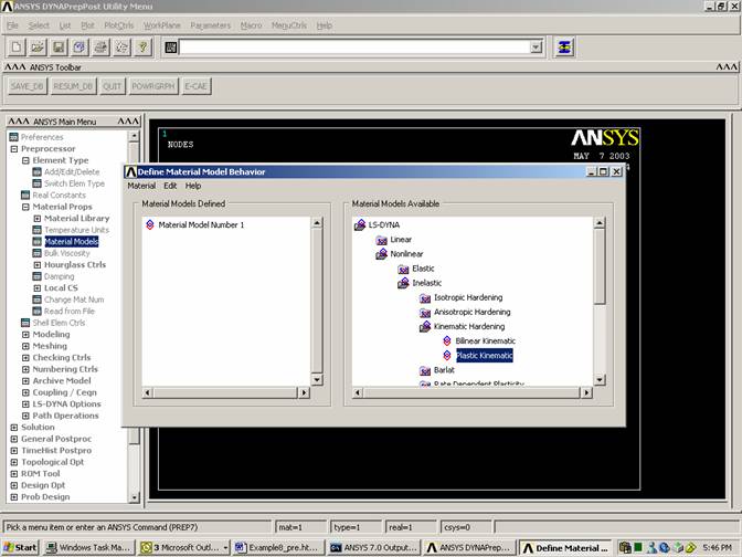
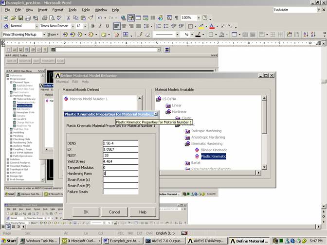
Define material type.
Inelastic, perfectly plastic kinematic material is used for group #2 with the following characteristics:
Density (lb-sec2/in4) = 2.5E-4
Elastic Modulus (lb/in2) = 1.05E7
Yield Strength (g/msec2 cm) = 4.4E4
Poisson’s Ratio = 0.33
Hardening Parameter = 1.0
Hardening Modulus (lb/in2) = 0.0
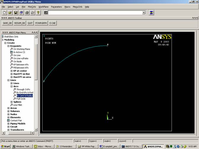
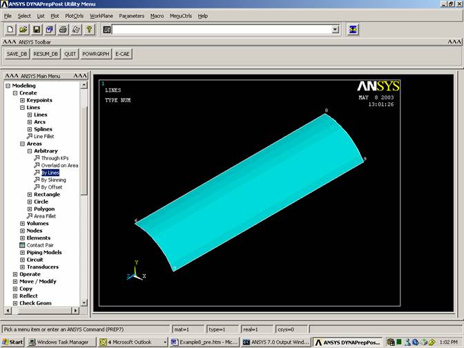
Create the shell
Create keypoints to describe the
arc
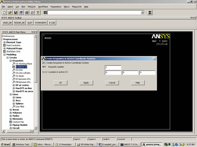
Click Apply
Repeat with:
Point #2 at 0,2.93,0
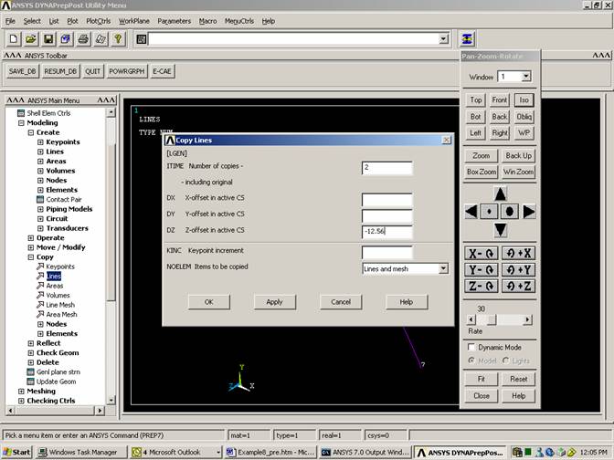
Create the arc (by center and radius)
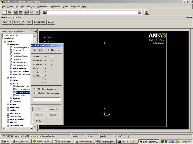
Select origin
Select other point
Enter angle as 60 degrees
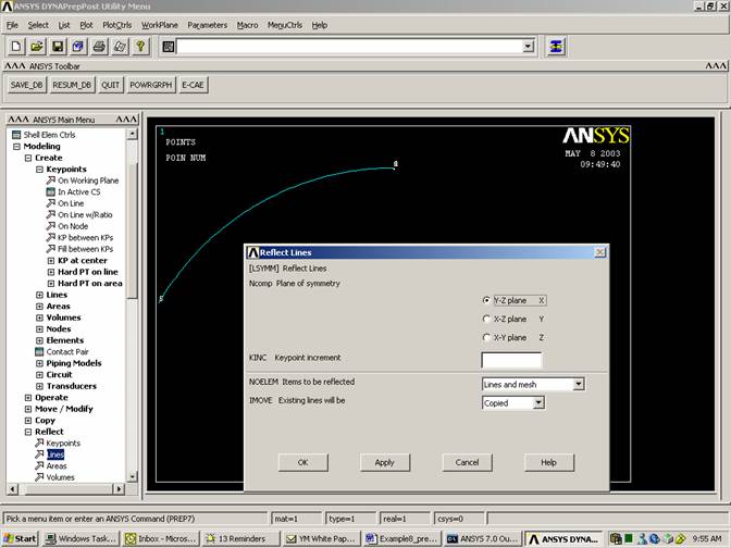
If we need the arc in the first quadrant, we should reflect it.
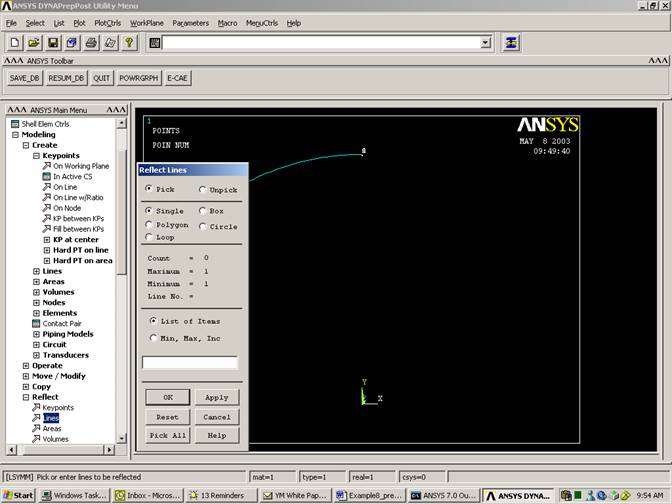
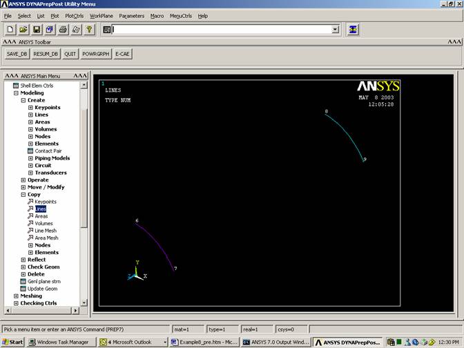
Select the arc
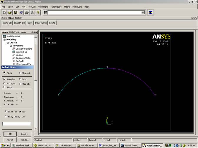
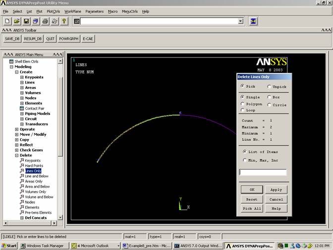
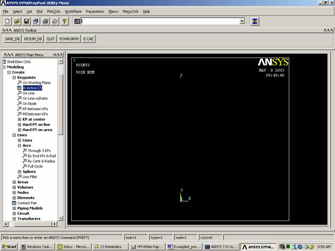
Plot
Replot
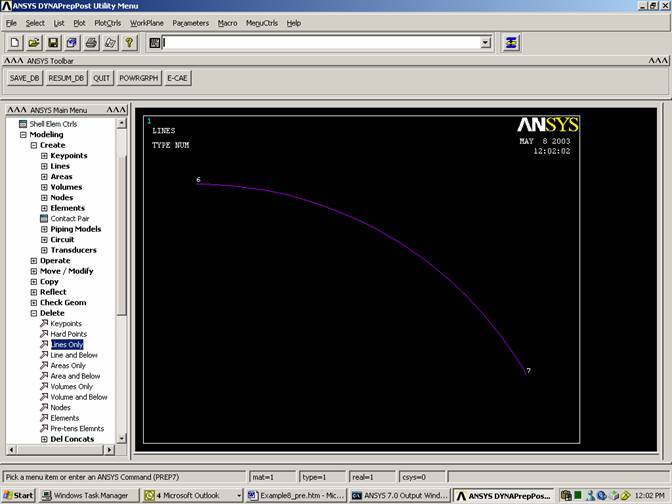
PlotCtrls
Pan, Zoom, Rotate
Iso
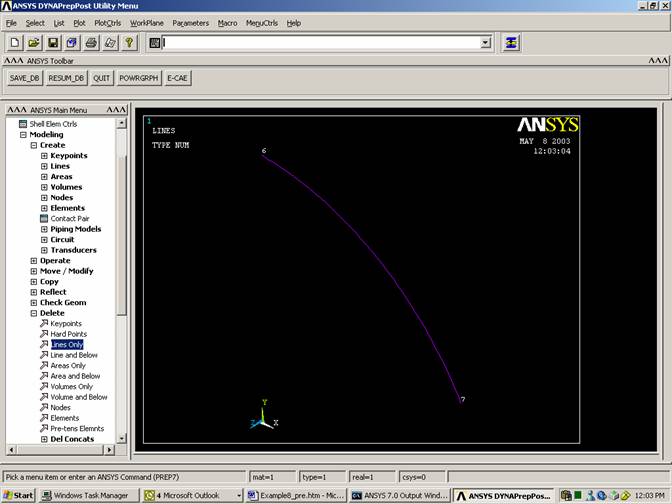
Note: It may be a good idea if duplicate keypoints are deleted to make selection of points easier.
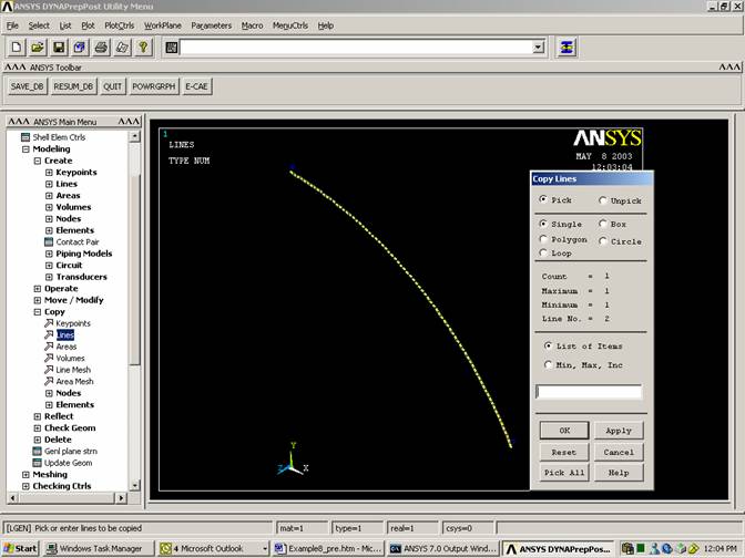
Create two more lines to make the patch
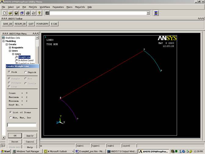
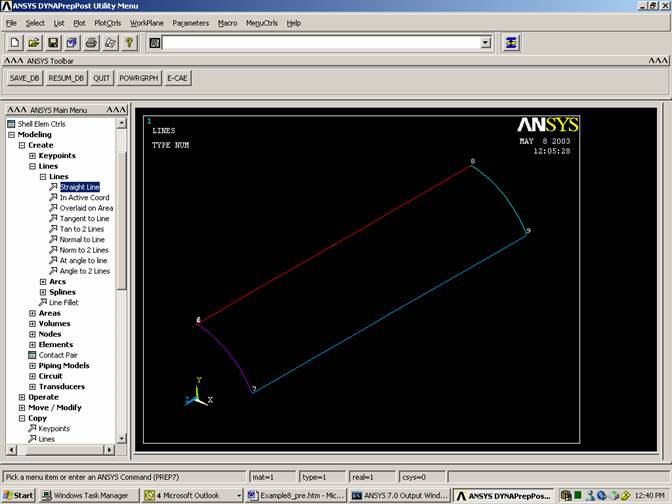
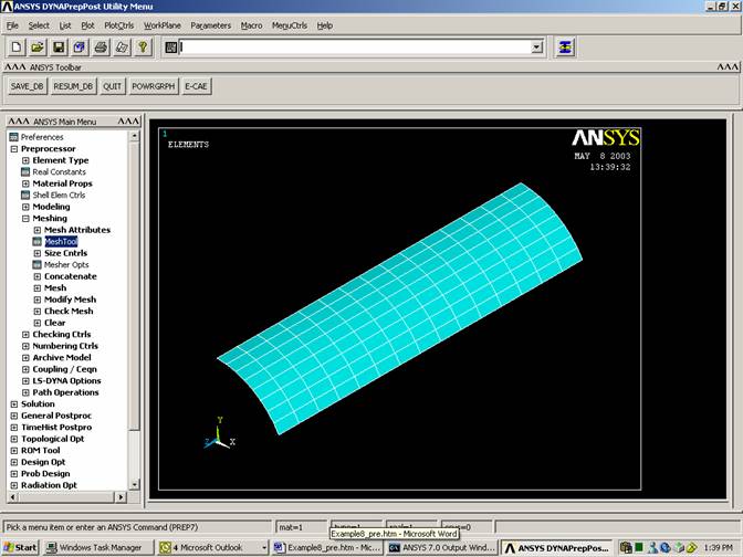
Create Area
Select the 4 lines
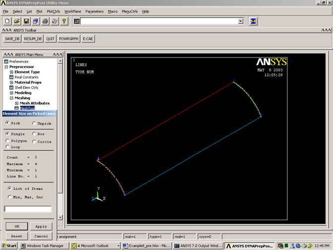
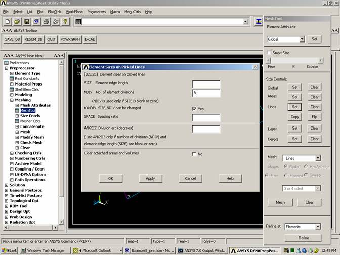
Meshing
Plot
Lines
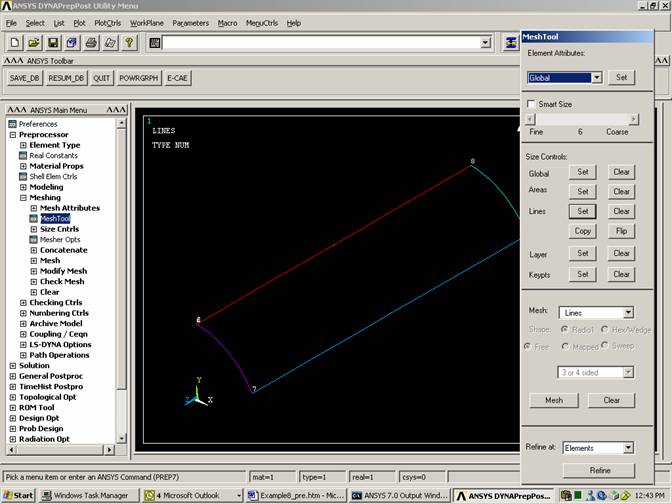
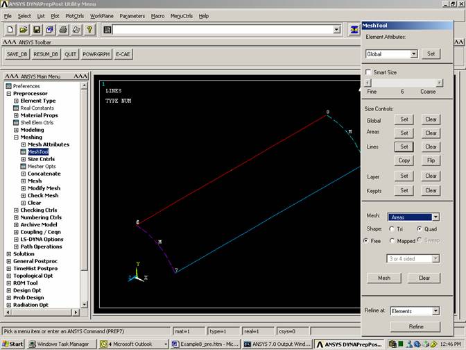
Click on Areas
Select area
Add Boundary Conditions
Plot
Elements
PlotCtrls
Pan, Zoom, Rotate
Click on Top

Choose the nodes in the y-z plane
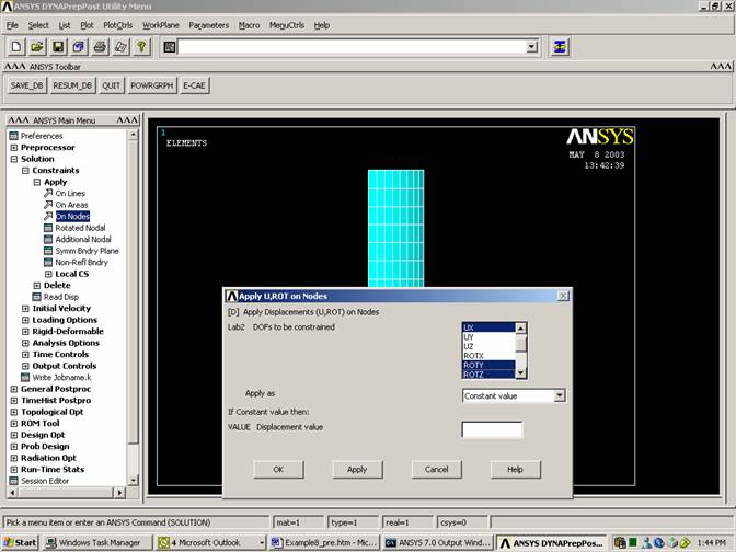
Choose the nodes on the lower edge
Constrain all degrees of freedom

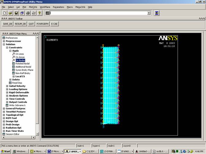
Choose nodes on the two remaining edges
Constrain them in the x and y directions
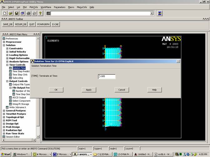
Set Simulation Time
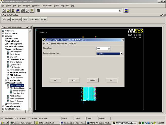
Set Output Controls
(You can specify the output to either ANSYS, LS-DYNA, or both)
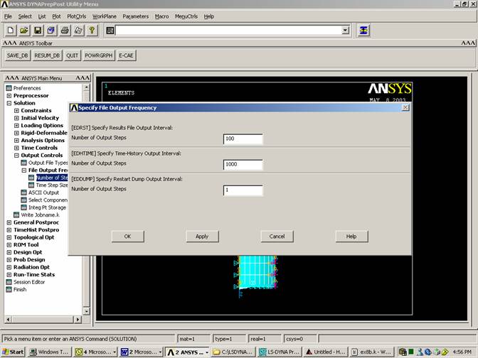
Specify the Output
Frequency
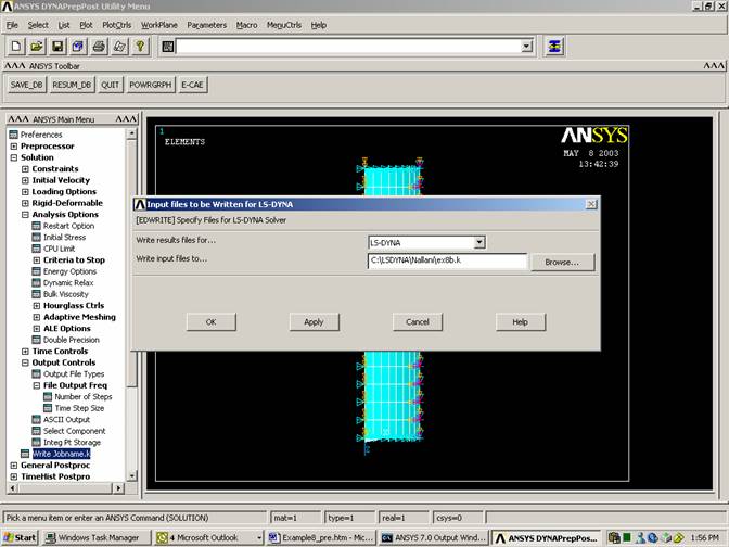
Save File (It is very important to save in ANSYS format (*.db) since it cannot read DYNA format (*.k))
File
Save As
ex8b.db
Initial Velocity:
Initial velocity can be input by creating boxes that enclose the nodes within specific segments of your model. You can do this by adding the following to your *.k program. In this section one box is created:
·
Place the text near the end of the *.k file.
$
$ define section
$
*DEFINE_BOX
$ i f
f
f
f
f
f
$ boxid xmm xmx ymn ymx zmn zmx
2,-0.01,2.5,1.49,2.95,-12.5,-.01
$ initial condition
section
$
*INITIAL_VELOCITY
$ i i i
$ nsid nsidex boxid
0 0 2
$ f f f f f f
$ vx vy vz wx wy wz
0.0,-5650.0,0.0,0.0,0.0,0.0