Interfacing ANSYS and LS-DYNA
Sample Problem #6: Rigid Mass Falling on a plate supported by Beams
Pre-Processing
Open ANSYS
· ANSYS Interface has pull-down menu on the top. These menus cover functions such as plotting, display, and selection of entities. Help menu is also at this location.
· ASNSY has also menus on the left side of the screen. These menus cover pre-processing, processing, and post-processing.
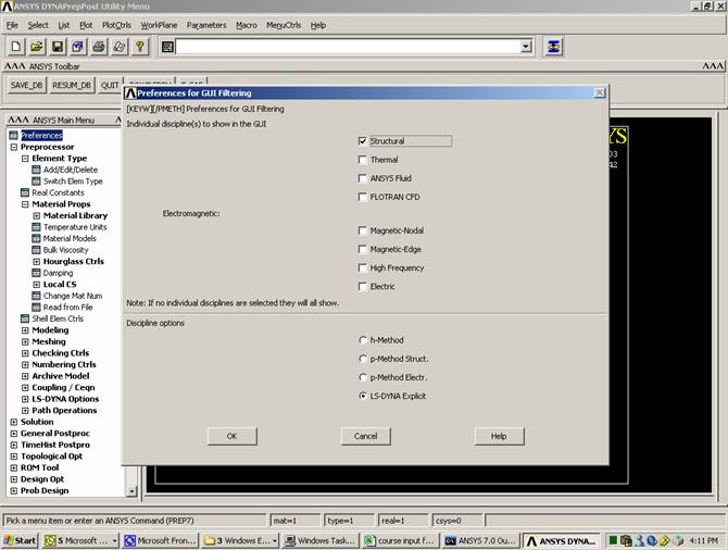
· ANSYS needs to know that you are planning to create LS-DYNA model. That is why you need to select LS-DYNA Explicit in the Preferences
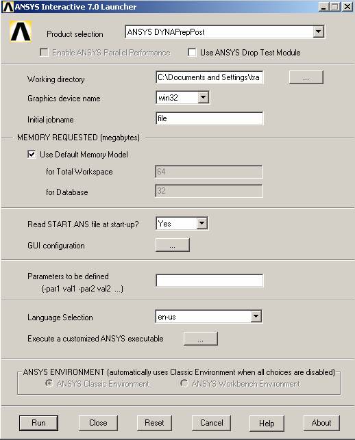
In Windows, select Start
Programs
ANSYS Release 7.0
ANSYS Interactive
In Product Selection, choose: ANSYS DYNAPrepPost
Run
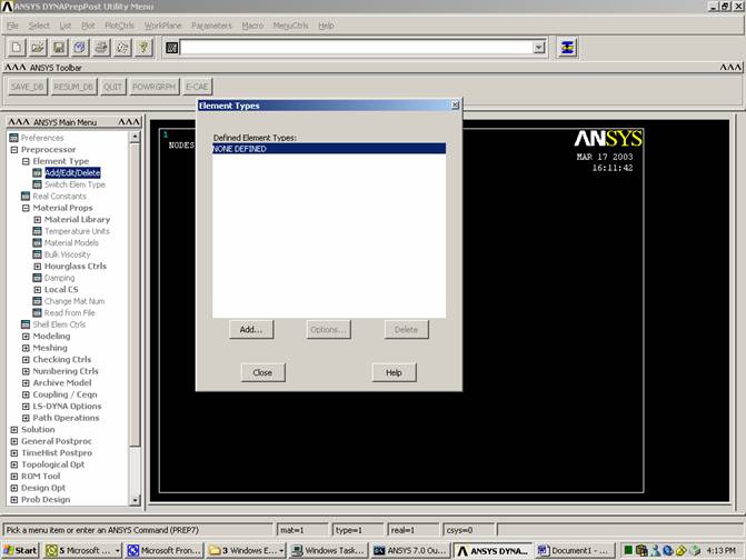
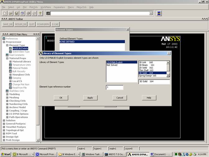
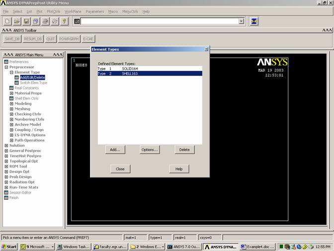
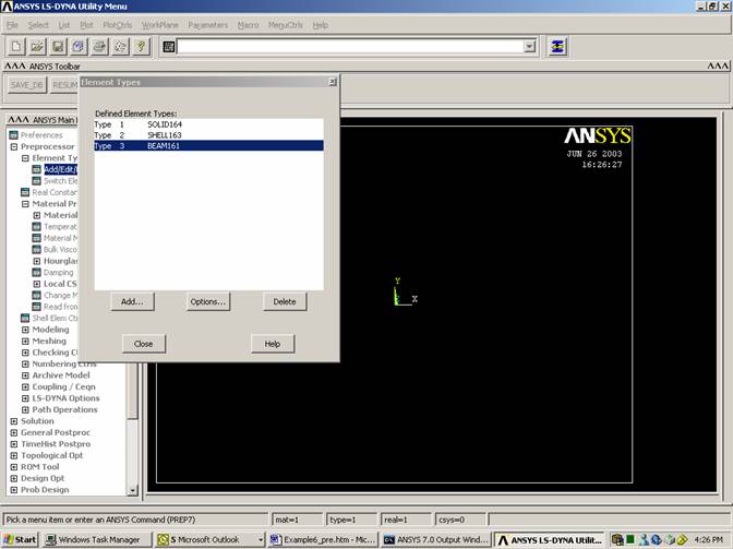
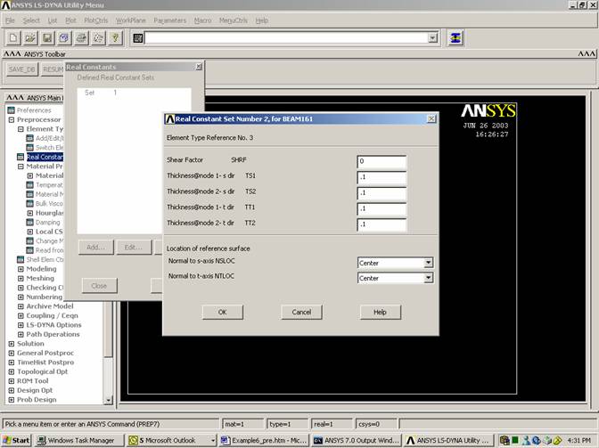
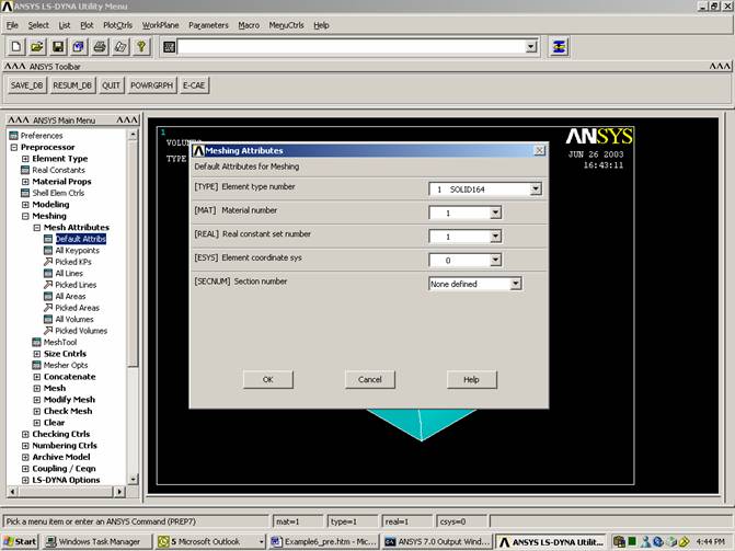
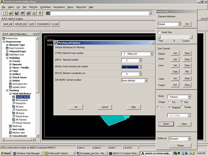
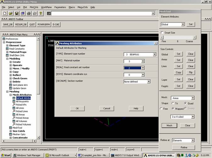
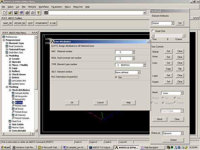
Define element type
Element Group #1: solid element,
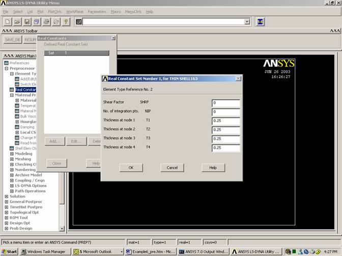
Element Group #2: shell element (thickness=0.25),
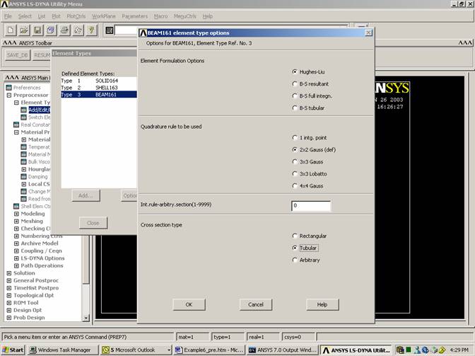
Element Group #3: beam element (thickness=0.5)
Assign Thickness to the Plates
Define material type.
Rigid material is used for group #1 with the following characteristics:
Density (lb sec2/in4) = 2.77x10⁻³
Elastic Modulus (lb/in2) = 3.0x10⁸
Poisson’s Ratio = 0.3
Transnational constraint = x and y displacement
Rotational constraints = all rotations
Rigid material is used for group #2 with the following characteristics:
Density (lb sec2/in4) = 2.77x10⁻⁴
Elastic Modulus (lb/in2) = 3.0x10⁷
Poisson’s Ratio = 0.3
Inelastic, plastic kinematic material is used for group #3 with the following characteristics:
Density (lb sec2/in4) = 2.77x10⁻⁴
Elastic Modulus (lb/in2) = 3.0x10⁷
Tangent Modulus (lb/in2) = 3.0x10⁴
Poisson’s Ratio = 0.3
Yield Strength (lb/in2) = 5.0x10⁴
Hardening Parameter = 1.0
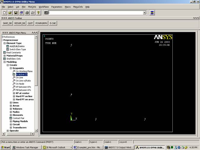
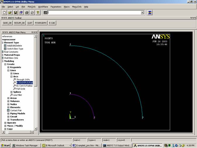
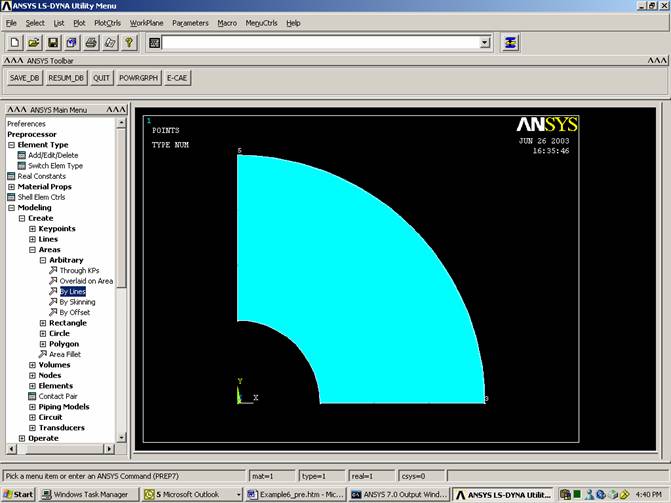
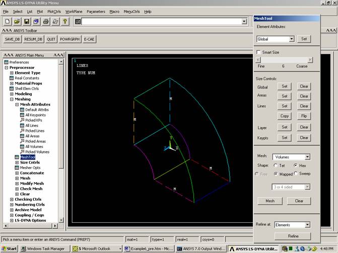
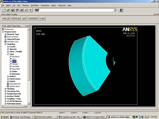
Create the solid
Create key points corresponding to two quarter circles in the positive-positive quarter of the x-y plane of radii 1 and 3 inches respectively.
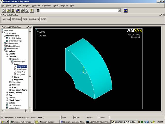
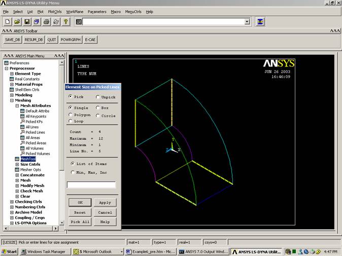
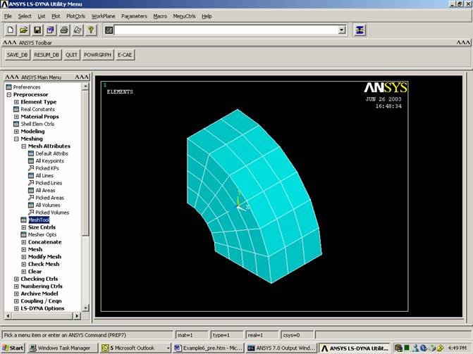
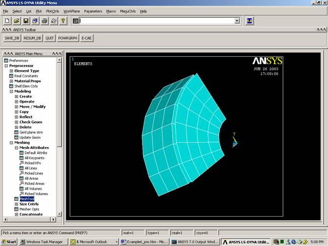
Meshing the volume
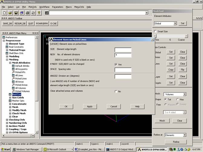
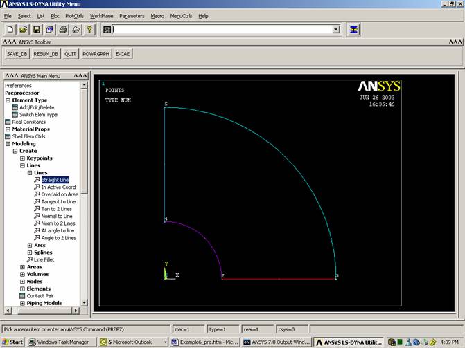
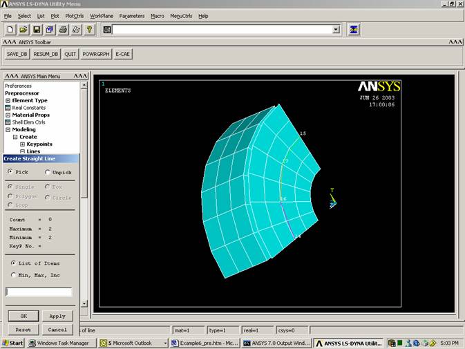
Create the plate
Similar to meshing the volume, in mesh tools, choose lines, pick the straight edges of the plate, and divide them into 4 sections.
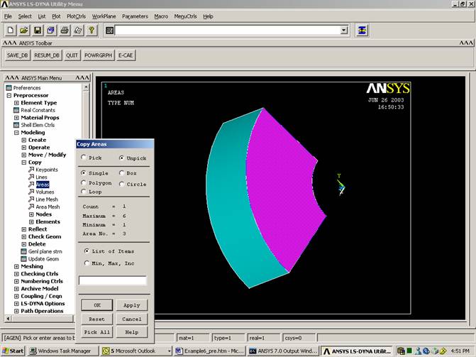
Create the Beams
Copy the three lines by distance DZ=-2
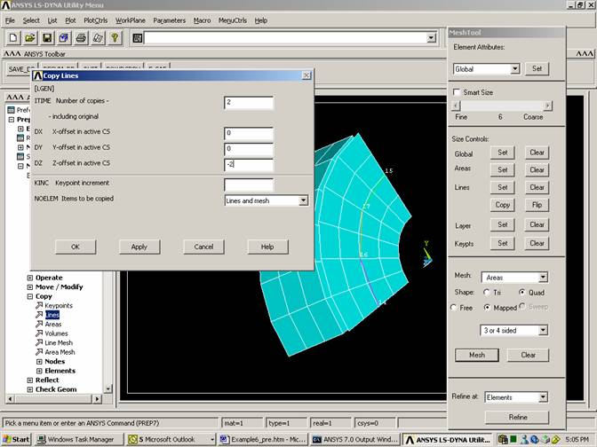
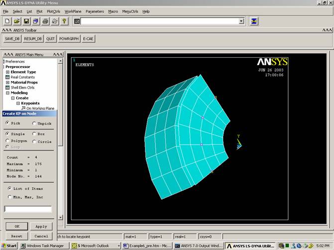
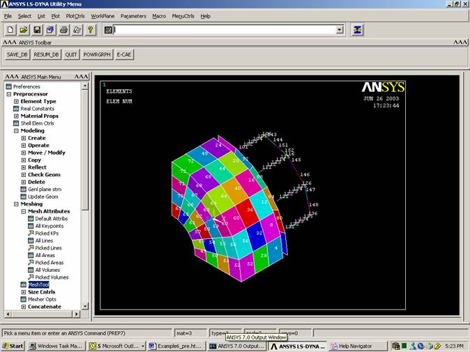
Mesh the lines
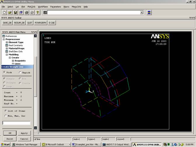
Choose the keypoint at the origin (#1) as it is not attached to any line.
Repeat the same procedure for meshing the lines at the bottom of the model and the plate. Use 2 elements per line.
Use Numbering in PlotCrls to add element number
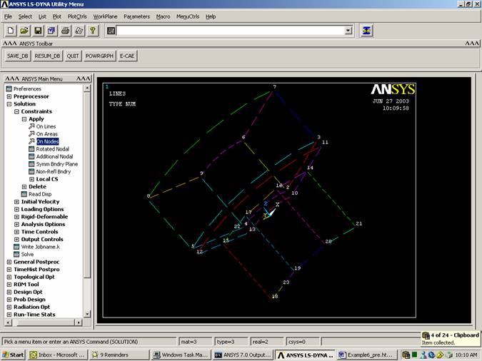
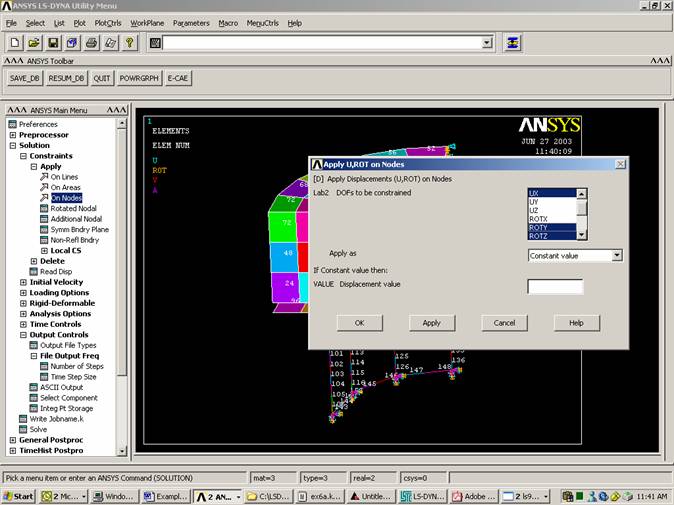
Boundary Conditions
Plot
Lines
PlotCtrls
Pan, Zoom, Rotate
Dynamic Mode
Click on right mouse button to adjust view
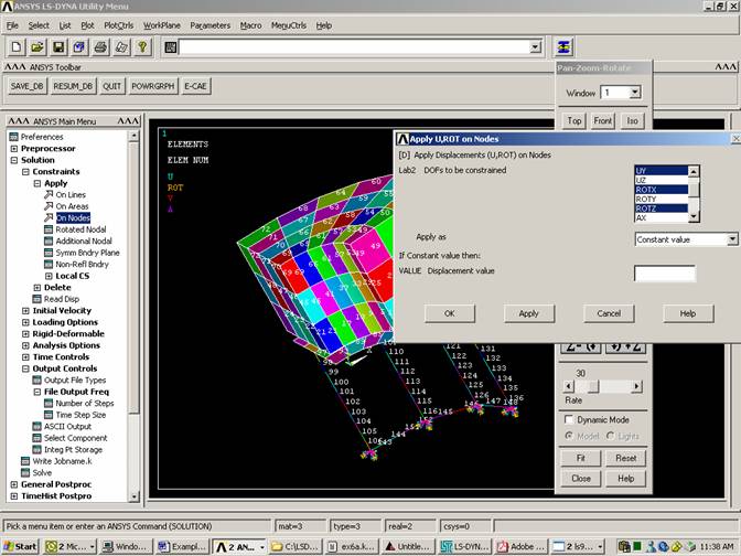
Choose the nodes on the bottom end of the vertical beams. Restrict them completely.
Add boundary conditions to nodes on planes of symmetry
Set Time Controls

Set Output Controls
(You can specify the output to either ANSYS, LS-DYNA, or both)
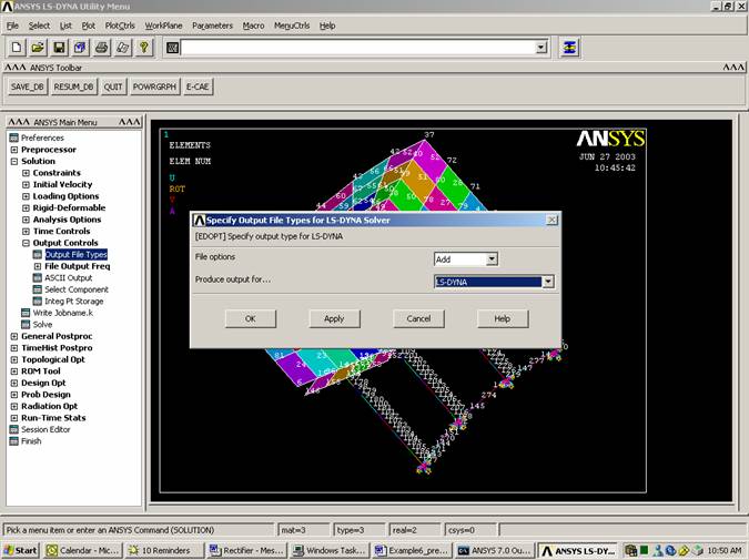
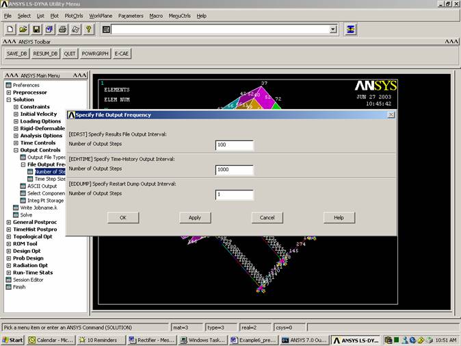
Specify the Output
Frequency
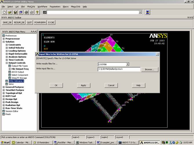
Save File (It is very important to save in ANSYS format (*.db) since it cannot read DYNA format (*.k))
File
Save As
Sample4a.db
Initial Velocity:
Initial velocity and contact can be input in ANSYS by creating component and assigning the initial velocity or contact specification to this component. It is much easier to create boxes that enclose the nodes within specific segments of your model. You can do this by adding the following to your *.k program. In this section two boxes are created:
·
·
Place the text near the end of the *.k file.
$
$ define section
$
*DEFINE_BOX
$ i f f f f f f
$ boxid xmn xmx ymn ymx zmn zmx
1-7.302E-07 3.0-7.302E-07 3.0
-0.0001 2.10000
*DEFINE_BOX
$ i f f f f f f
$ boxid xmn xmx ymn ymx zmn zmx
2-7.302E-07 3.0-7.302E-07 3.0
-2.3 -0.19
$
$ initial condition
section
$
*INITIAL_VELOCITY
$ i i i
$ nsid nsidex boxid
0 0 1
$ f f f f f f
$ vx vy vz wx wy wz
0.0
0.0
-1000 0.0 0.0 0.0
*INITIAL_VELOCITY
$ i i i
$ nsid nsidex boxid
0 0 2
$ f f f f f f
$ vx vy vz wx wy wz
0.0
0.0
0.0
0.0
0.0
0.0
Contact
Another method to
define contact
Define contact between the lower surface of the mass and the plate. Define also contact between the plate and the horizontal beams to force them to move together.
Place the text near the end of the *.k file.
*DEFINE_BOX
$ i f f f f f f
$ boxid xmn xmx ymn ymx zmn zmx
3,0.00,3.0,0.0,3.0,0.00,0.01
$
*DEFINE_BOX
$ i f f f f f f
$ boxid xmn xmx ymn ymx zmn zmx
4,0.00,3.0,0.0,3.0,-0.21,-0.20
$
*CONTACT_SURFACE_TO_SURFACE
$ ssid msid sstyp mstyp sboxid mboxid spr mpr
0 0 0 0 4 3 0 0
$ fs fd dc vc vdc penchk bt dt
0.000
0.000
0.000
0.000
0.000
0 0.000 0.100E+08
$ sfs sfm sst mst sfst sfmt fsf vsf
1.000
1.000
0.000 0.000 1.000
1.000
1.000
1.000
*CONTACT_TIED_NODES_TO_SURFACE
$ ssid msid sstyp mstyp sboxid mboxid spr mpr
0 0 0 0 4 4 0 0
$ fs fd dc vc vdc penchk bt dt
0.000
0.000
0.000
0.000
0.000
0 0.000 0.100E+08
$ sfs sfm sst mst sfst sfmt fsf vsf
1.000
1.000
0.000 0.000 1.000
1.000
1.000
1.000