Interfacing ANSYS and LS-DYNA
Sample Problem #4: Rigid Cylindrical Bar Moving Along the Z-Axis and
Impacting a Plate in the X-Y Plane that is Supported by Other Plates Normal to
It
Pre-Processing
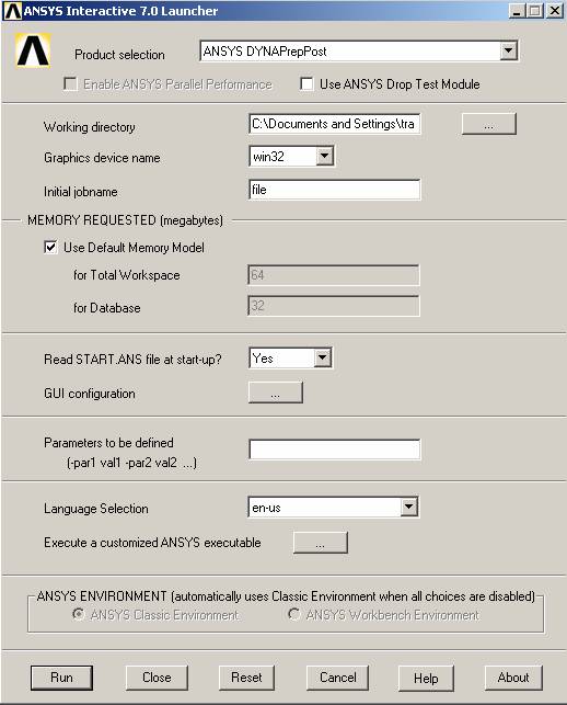
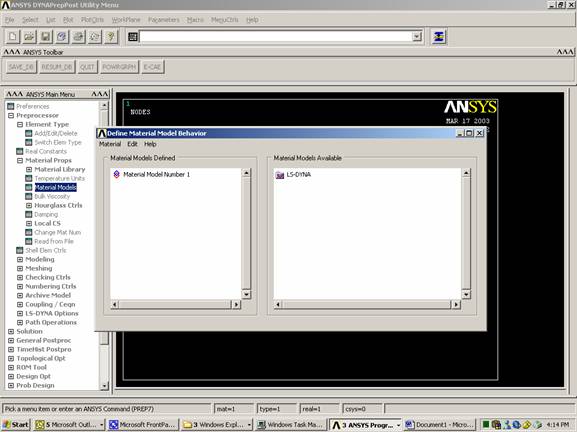
Open ANSYS
· ANSYS Interface has pull-down menu on the top. These menus cover functions such as plotting, display, and selection of entities. Help menu is also at this location.
· ASNSY has also menus on the left side of the screen. These menus cover pre-processing, processing, and post-processing.
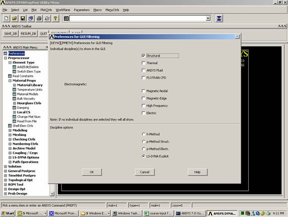
· ANSYS needs to know that you are planning to create LS-DYNA model. That is why you need to select LS-DYNA Explicit in the Preferences
In Windows, select Start
Programs
ANSYS Release 7.0
ANSYS Interactive
In Product Selection, choose: ANSYS DYNAPrepPost
Run
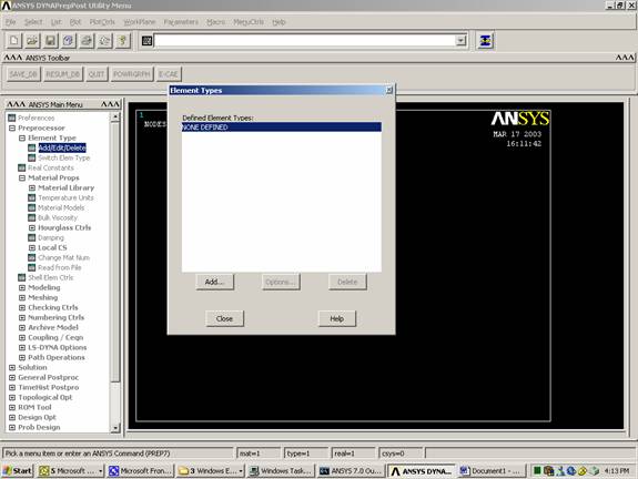
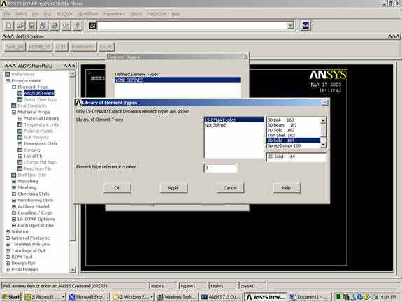
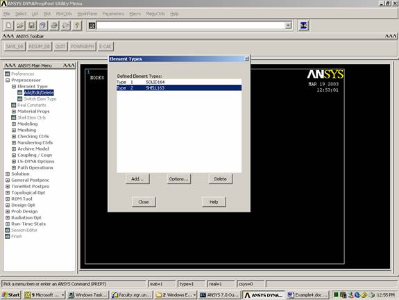
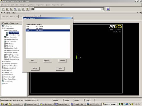
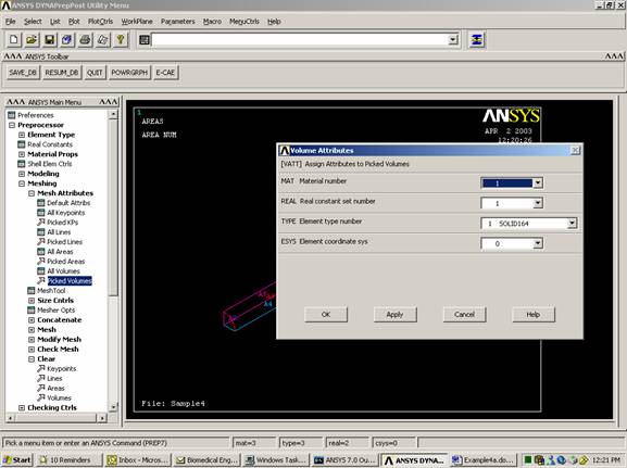
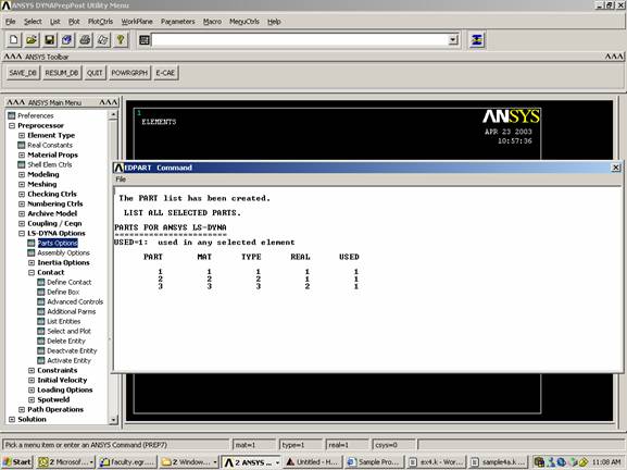
Define element type
Element Group #1: solid element,
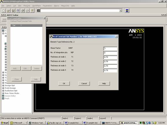
Element Group #2: shell element (thickness=0.79),
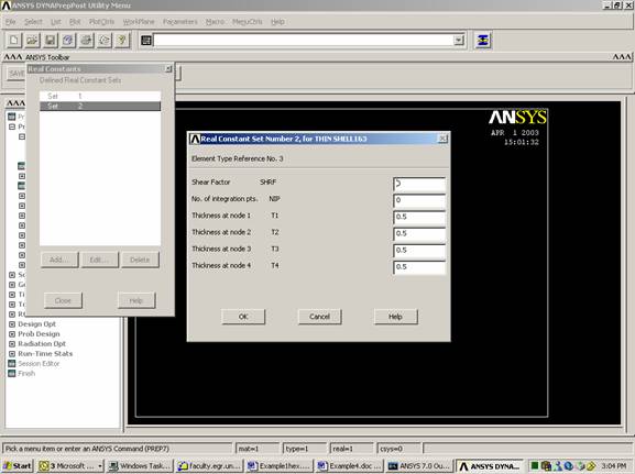
Element Group #3: shell element (thickness=0.5)
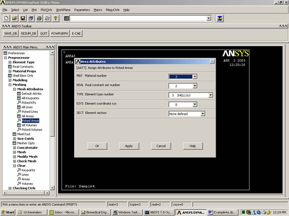
Assign Thickness to
the Plates
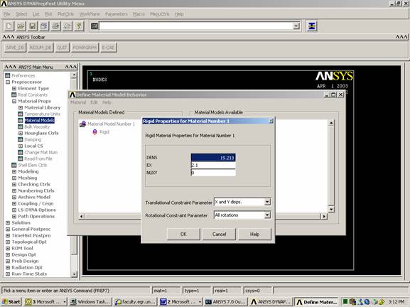
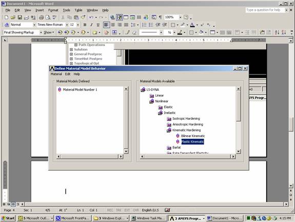
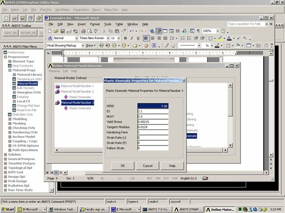
Define material type.
Rigid material is used for group #1 with the following characteristics:
Density (g/cm3) = 19.218
Elastic Modulus (g/msec2 cm) = 2.1
Poisson’s Ratio = 0.0
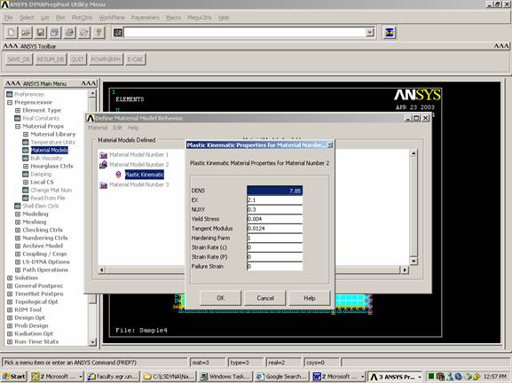
Inelastic, plastic kinematic material is used for group #2 with the following characteristics:
Density (g/cm3) = 7.85
Elastic Modulus (g/msec2 cm) = 2.1
Tangent Modulus (g/msec2 cm) = 1.24x10⁻²
Yield Strength (g/msec2 cm) = 4.0x10⁻³
Poisson’s Ratio = 0.3
Hardening Parameter = 1.0
Inelastic, plastic kinematic material is used for group #3 with the following characteristics:
Density (g/cm3) = 7.85
Elastic Modulus (g/msec2 cm) = 2.1
Tangent Modulus (g/msec2 cm) = 1.24x10⁻²
Yield Strength (g/msec2 cm) = 2.15x10⁻³
Poisson’s Ratio = 0.3
Hardening Parameter = 1.0
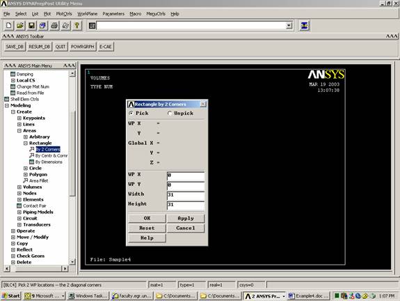
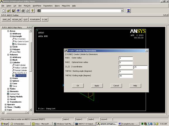
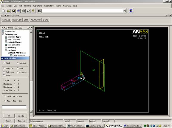
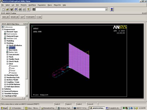
Create the plates
WorkPlane
Offset Work Plane by Increment
Rotate +Y (90 degrees)
Create rectangle (0,0,5,31)
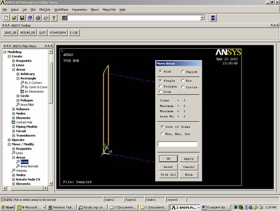
shift by 25,0,0
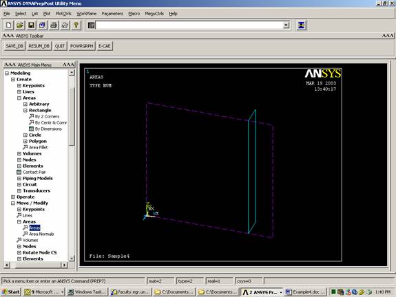
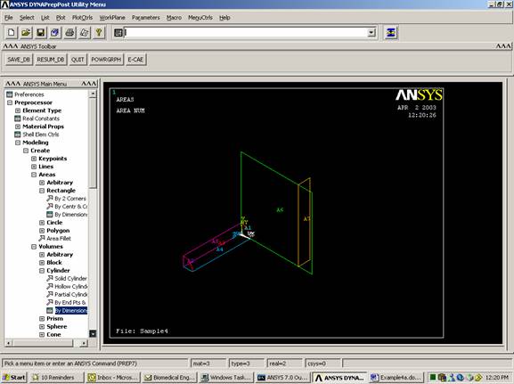
Create Volume
WorkPlane
Offset Work Plane by Increment
Rotate -Y (90 degrees)

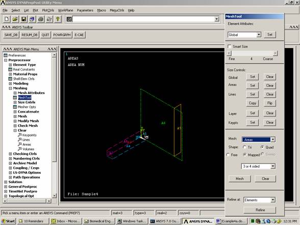
Note: Turn off smart size if it is on.
Plot
Areas
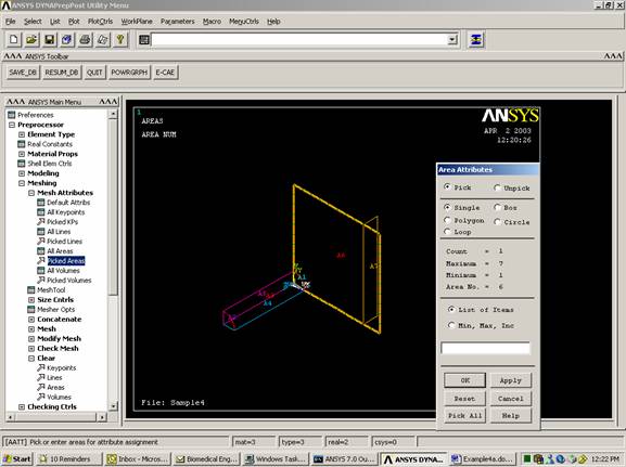
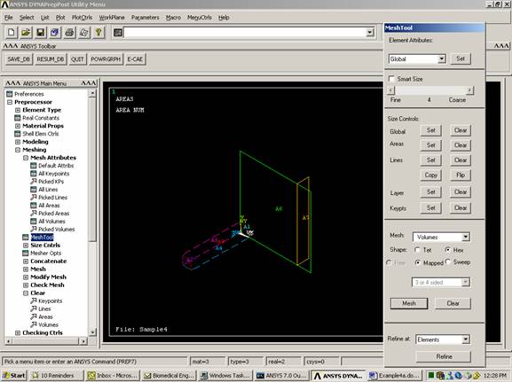
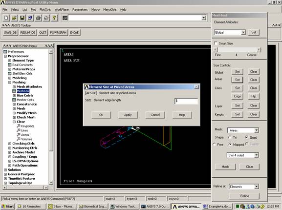
Select Mesh Tool
Set Areas
Select the big square
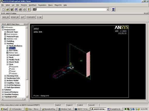
Plot
Areas
Select Mesh Tool
Set Areas
Select the small rectangle
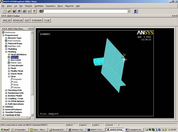
Plot
Elements
PlotCtrls
Pan, Zoom, Rotate
Click on Dynamic Mode
Use right mouse button
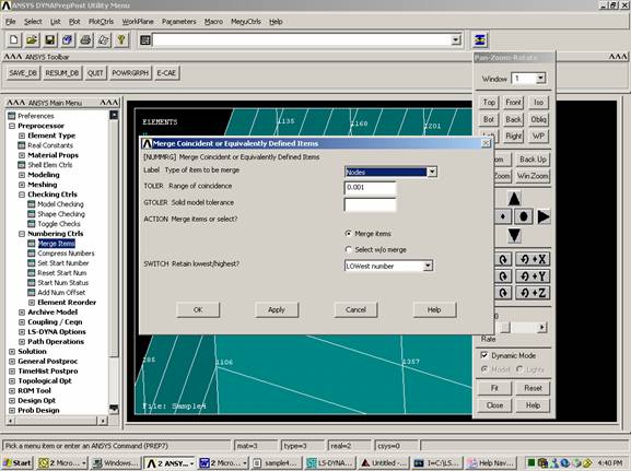
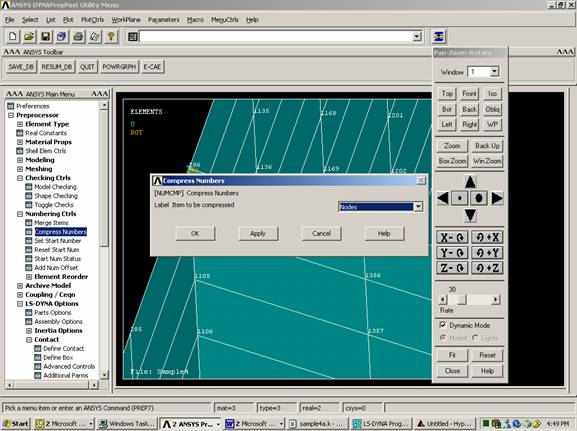
Merge nodes
Some of the nodes are in the same location. They should be merged.
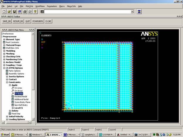
Boundary conditions
PlotCtrls
Pan, Zoom, Rotate
Click on right
Choose the nodes on the bottom of the smaller plate. Restrict them completely
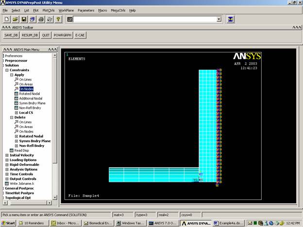

Click on front
Choose the nodes on the left edge of the plates. Restrict them UX, RY, RZ.
Choose the nodes on the lower edge of the plate. Restrict them in the UY, RX, RZ
Contact
Make contact between a 4x4 square on the horizontal plate
and the lower surface of the cylinder.


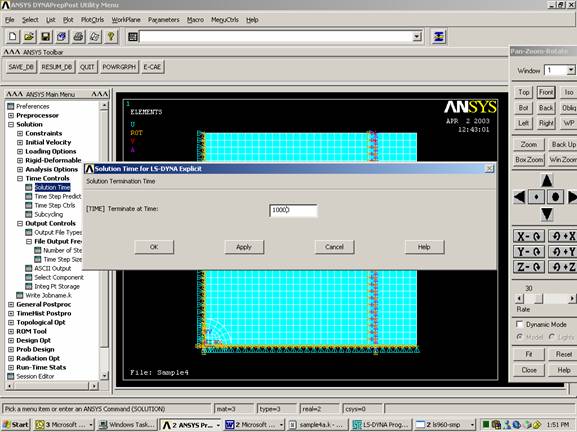
Set Time Controls
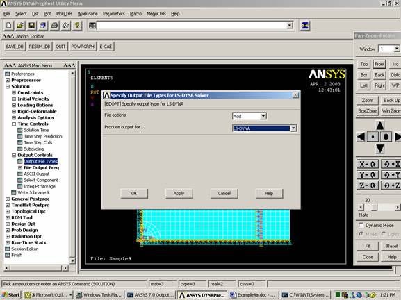
Set Output Controls
(You can specify the output to either ANSYS, LS-DYNA, or both)
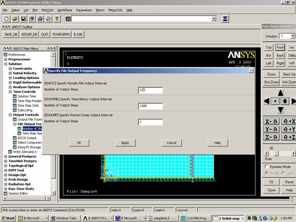
Specify the Output
Frequency
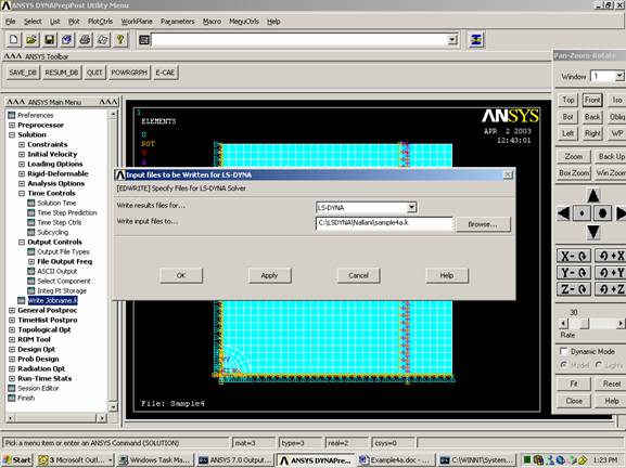
Save File (It is very important to save in ANSYS format (*.db) since it cannot read DYNA format (*.k))
File
Save As
Sample4a.db
Initial Velocity:
Initial velocity and contact can be input in ANSYS by creating component and assigning the initial velocity or contact specification to this component. It is much easier to create boxes that enclose the nodes within specific segments of your model. You can do this by adding the following to your *.k program. In this section two boxes are created:
·
·
Place the text near the end of the *.k file.
$
$ define section
$
*DEFINE_BOX
$ i f f f f f f
$ boxid xmm
xmx ymn ymx
zmn zmx
1-7.302E-07 31.0000-7.302E-07 31.0000
0.0 5.00000
*DEFINE_BOX
$ i f f f f f f
$ boxid xmm
xmx ymn ymx
zmn zmx
2-1.565E-07 4.00000-1.565E-07 4.00000
5.00500 30.0000
$
$ initial condition
section
$
*INITIAL_VELOCITY
$ i i i
$ nsid nsidex
boxid
0 0 1
$ f f f f f f
$ vx vy
vz wx wy wz
0.0
0.0 0.0 0.0
0.0 0.0
*INITIAL_VELOCITY
$ i i i
$ nsid nsidex
boxid
0 0 2
$ f f f f f
f
$ vx vy vz wx wy wz
0.0
0.0-1.800e-03 0.0 0.0
0.0
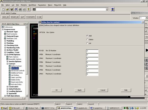
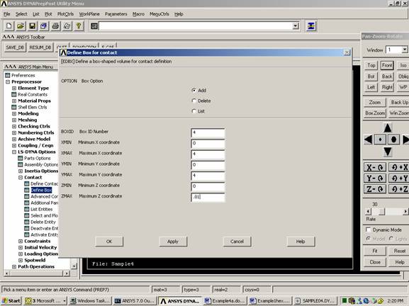
Contact
Another method to
define contact
Define contact between the lower surface of the cylinder and a 4x4 square patch of the horizontal plate. Place the text near the end of the *.k file.
$$$$$$$$$$$$$$$$$$$$$$$$$$$$$$$$$$$$$$$$$$$$$$$$$$$$$$$$$$$$$$$$$$$$$$$$$$$$$$$$
$ CONTACT
DEFINITIONS $
$$$$$$$$$$$$$$$$$$$$$$$$$$$$$$$$$$$$$$$$$$$$$$$$$$$$$$$$$$$$$$$$$$$$$$$$$$$$$$$$
$
*DEFINE_BOX
$ i f f f f f f
$ boxid xmm
xmx ymn ymx
zmn zmx
3,0.00,4.0,0.0,4.0,0.00,0.01
$
*DEFINE_BOX
$ i f f f f f f
$ boxid xmm
xmx ymn ymx
zmn zmx
4,0.00,4.0,0.0,4.0,-1.00,0.0
$
*CONTACT_TIED_SURFACE_TO_SURFACE
0 0 0 0 3 4 0 0
0.000
0.000 0.000 0.000
0.000 0 0.000 0.1000E+08
1.000
1.000 0.000 0.000
1.000 1.000 1.000
1.000