Interfacing ANSYS and LS-DYNA
Sample Problem #1: Cylindrical Bar Impacting a Rigid Wall
Pre-Processing
Open ANSYS
· ANSYS Interface has pull-down menu on the top. These menus cover functions such as plotting, display, and selection of entities. Help menu is also at this location.
· ASNSY has also menus on the left side of the screen. These menus cover pre-processing, processing, and post-processing.
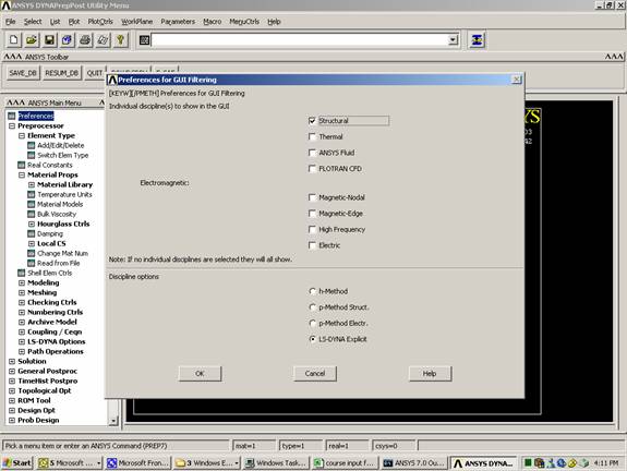
· ANSYS needs to know that you are planning to create LS-DYNA model. That is why you need to select LS-DYNA Explicit Explicit in the Preferences
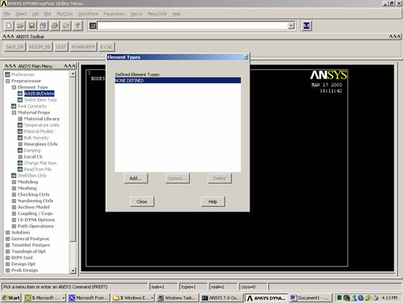
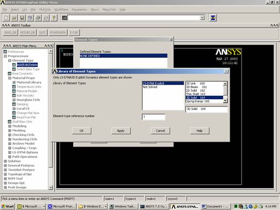
Define element type
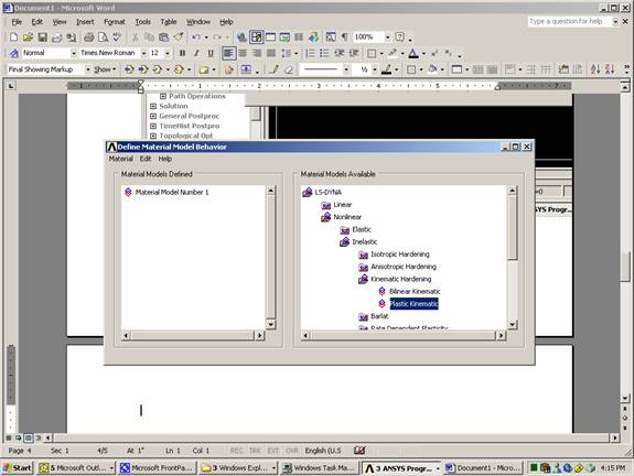
Define material type.
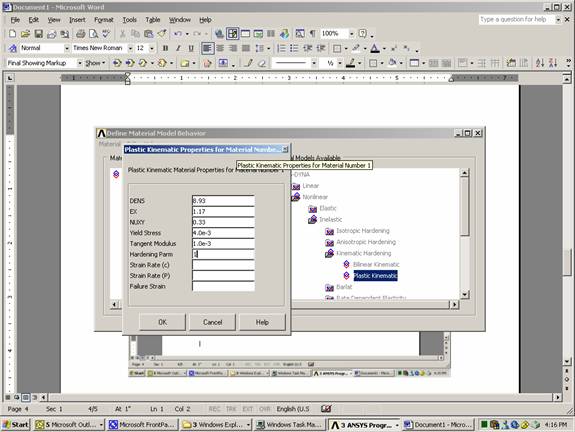
Material model used is inelastic, plastic kinematic with the following characteristics:
Density (g/cm3) = 8.93
Elastic Modulus (g/msec2 cm) = 1.17
Tangent Modulus (g/msec2 cm) = 1.0x10⁻³
Yield Strength (g/msec2 cm) = 4.0x10⁻³
Poisson’s Ratio = 0.33
Hardening Parameter = 1.0

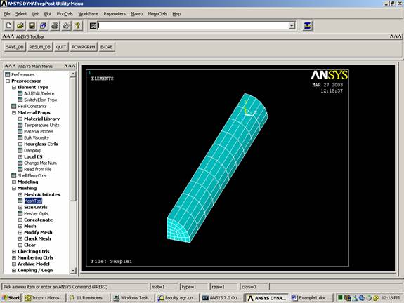
Import a Parasolid file (Note: You can create the quarter cylinder volume in ANSYS using Modeling menu)
File
Import
Para…
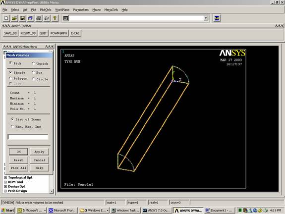
Mesh Volume
Note: Once the
volume becomes more complicated, hex elements will not work and tetrahedral
elements become the only choice 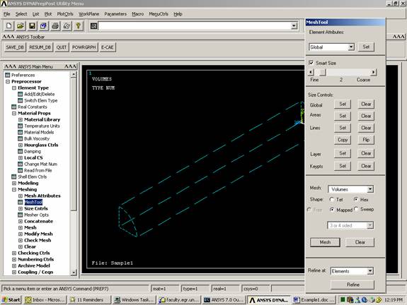
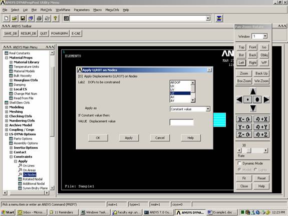
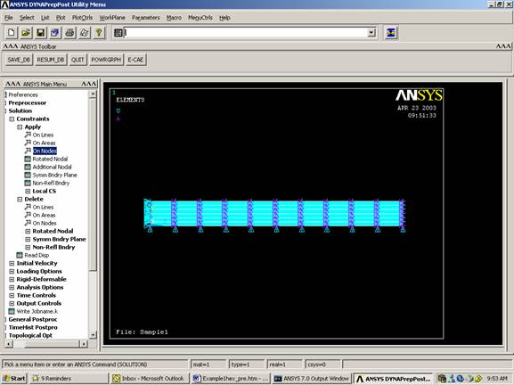
Add Boundary
Conditions
These are the boundary conditions:
- The surface at the origin cannot move in the z-direction
- The two surface of symmetry cannot move in the normal direction
PlotCtrls
Pan Zoom Rotate
Front
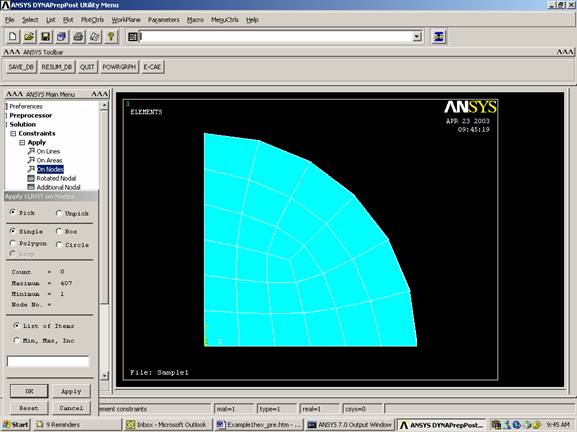
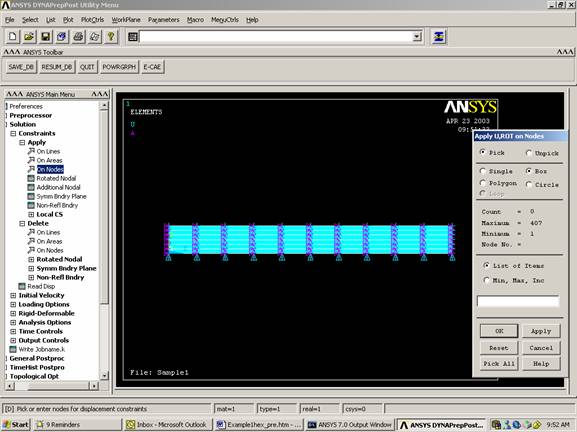
Select nodes on the vertical edge
Restrict these nodes in UX, AY, and AZ
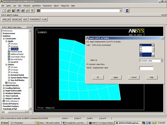
Select nodes on the horizontal edge
Restrict these nodes in UY, AX, and AZ
PlotCtrls
Pan Zoom Rotate
Left
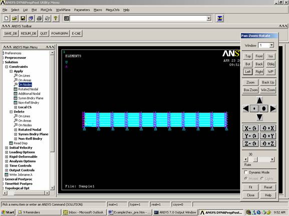
Select nodes on the left edge
Restrict them in UZ
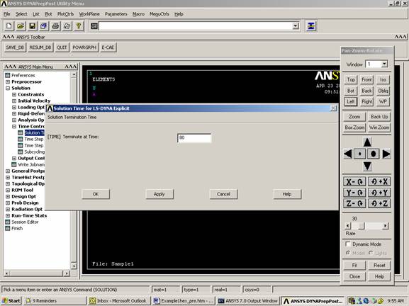
Set Time Controls
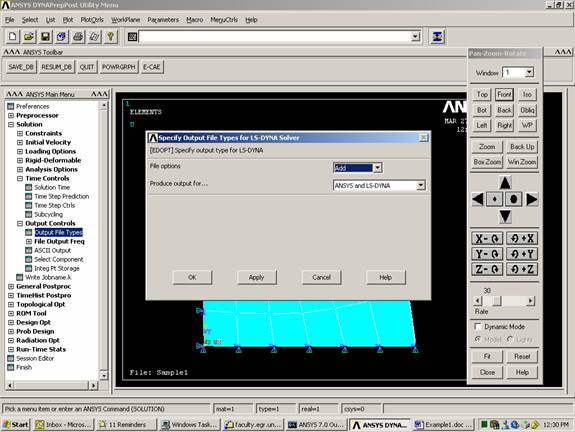
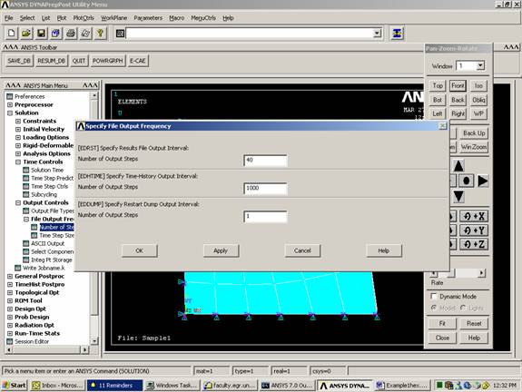
Set Output Controls
Specify the Output
(You can specify the output to either ANSYS, LS-DYNA, or both)
Save File (It is very important to save in ANSYS format (*.db) since it cannot read DYNA format (*.k))
File
Save As
Sample1hx.db
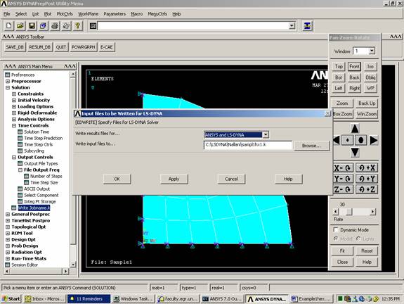
Note: You will
get warning that there is no explicit load defined. Ignore it since we will add
the load outside ANSYS.
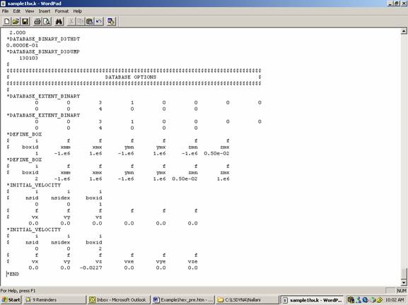
Initial Velocity:
Initial velocity and contact can be input in ANSYS by creating component and assigning the initial velocity or contact specification to this component. It is much easier to create boxes that enclose the nodes within specific segments of your model. You can do this by adding the following to your *.k program. In this section two boxes are created:
· Box #1 encloses the surface at the origin
· Box #2 encloses all other nodes
Place the text near the end of the *.k file.
*DATABASE_EXTENT_BINARY
0 0 3 1 0 0 0 0
0 0 4 0 0 0
*DEFINE_BOX
$ i f f f f f f
$ boxid xmm xmx ymn ymx zmn zmx
1
-1.e6 1.e6 -1.e6
1.e6 -1.e6 0.50e-02
*DEFINE_BOX
$ i f
f f f f f
$ boxid xmm xmx ymn ymx zmn zmx
2
-1.e6 1.e6 -1.e6
1.e6 0.50e-02 1.e6
*INITIAL_VELOCITY
$ i i i
$ nsid nsidex boxid
0 0 1
$ f f f f f f
$ vx vy vz
0.0
0.0
0.0
0.0
0.0
0.0
*INITIAL_VELOCITY
$ i i i
$ nsid nsidex boxid
0 0 2
$ f f f f f f
$ vx vy vz vxe vye vze
0.0
0.0
-0.0227 0.0 0.0 0.0