Overview of the ALGOR System
First screen in Algor Superdraw III:
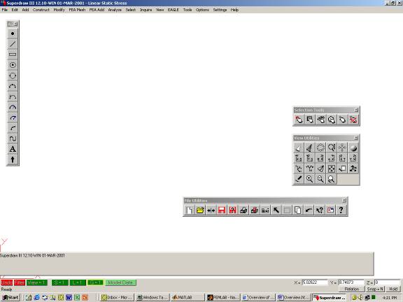
Step1 Draw the Geometry of the Model
Geometry can be drawn in other programs such as AutoCad and imported or drawn directly in ALGOR. The process entails:
- Defining overall dimensions of the model.
- Defining global coordinate frame.
Step2 Apply Forces and Boundary Conditions
Use FeaAdd in ALGOR to add forces and displacement boundary conditions. Each node can have up to six degrees of freedom:
three translations (Txyz)
three rotations (Rxyz)
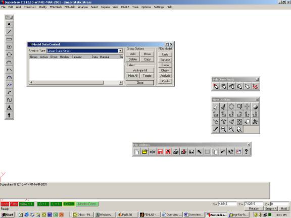
Step3 Define the Element Type and Properties
Use the Model Data button. Inside Model Data, user can input information relative to the characteristics of the model. Elements with the same properties are defined as members of the same Group. Groups can be defined in SuperDraw. Layer is used to differntiate between different geometric properties of beams.
Step4 Review the model
Use SuperView to view and evaluate the model for inconsistencies. Use Inquire to check dimensions, forces, or boundary conditions.
Step5 Compute Nodal Displacements and Element Stresses
Click on Analysis on Model Data to compute nodal displacements and element stresses.
Step6 View and Interpret the Results
Click on Results on Model Data to display the displacements and stresses using SuperView.