|
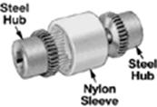
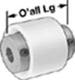
MEG 440 Fall 2004 Project #1 Design a gear and sleeve coupling with the specifications below (source: http://www.mcmaster.com/ ). You are to add the following modifications to the design: · Use a steel sleeve. · Use keys to connect shafts to hubs. You are to choose materials and dimensions such that components of the lift will not fail due to normal operating conditions. The following are brief overview of the major design steps: a. Create a sketch of your overall design that includes all relevant components. b. Use principles of statics to find the maximum forces that each component is subject to. c. Use the results of step (b) to calculate stresses on each component. d. Create a set of engineering drawings that can be used to manufacture the lift. It is preferred to use solid modeling at this step. e. Create STL files of your drawings to create a prototype of your design. f. Create list of components as explained in the first handout of the semester (http://www.me.unlv.edu/~mbt/440/Project_Format.html ).
|
|||||||||||||||||||||||||||||||||||||||||||||||||||||||||||||||||||||||||||||||||||||||||||||||||||||||||||||