Objective: Construct a quick return mechanism of the
shaper type with the following dimensions:
Crank: 1”
Fixed distance between link 2 and
link 4: 2”
Link 4: 5”
Link 5: 3”
Fixed Distance between link 4 and
the line of action of link6: 6”.
Housekeeping Preparations:
|
View |
|
|
|
|
Workspace |
|
|
|
|
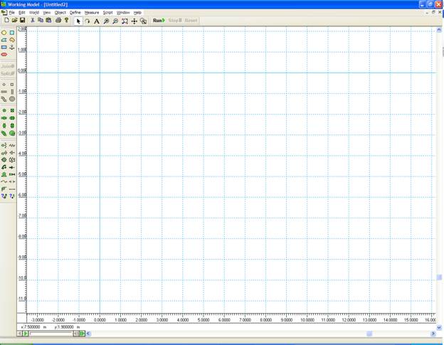
Ruler |
|
|
|
Grid Lines |
|
|
|
X,Y Axes |
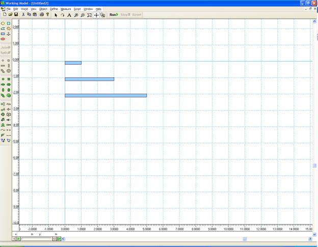
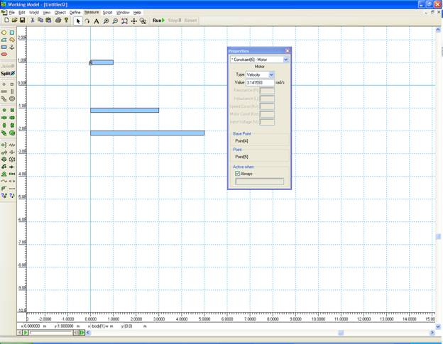
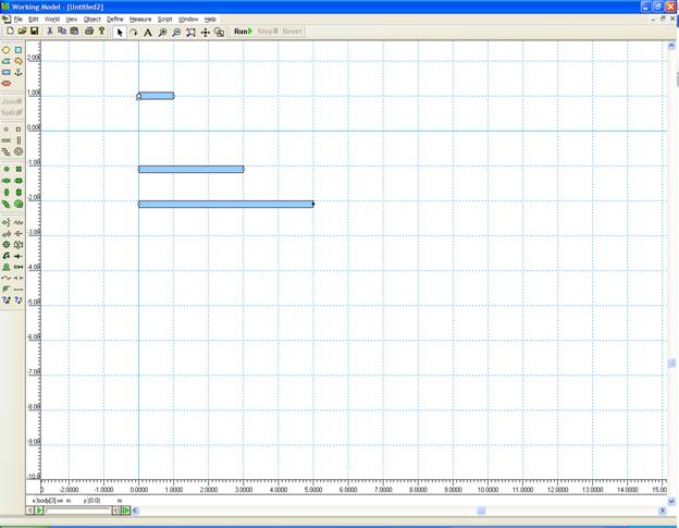
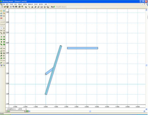
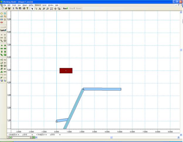
Click on the Rectangle Icon
Create three rectangle of width 0.2
and lengths of 1, 3, and 5 respectively. Dimensions will be shown in the lower
edge of the screen.
Click on the MOTOR Icon. Place
it the middle of the left edge of the shortest rectangle.
While the motor is highlighted,
click on the small windows in the lower left corner. Change the coordinated to
(0,1).
Double click on the motor icon.
Change the velocity to 3.1415927 rad/s
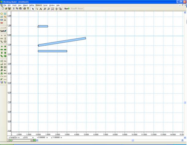
If you click RUN button the motor
and the attached link will rotate while the two other links will fall down.
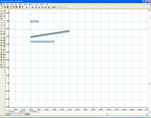
Use POINT element to add revolute
joints near the ends of the links. These points are where the joints will be
located.
Double click on each point to adjust
its coordinates if needed. You can use either global coordinates or local coordinates
(with respect to the center of the object).
Add a POINT at (-1,0). This will be
the fixed joint of link 4.
Click on a joint. Press shift and
click on the corresponding point on the other link.
Click on Slot Element (horizontal).
Add it to the longest link.
Connect point on the end of the
crank with the slot using JOIN. You may need to move links closer to each other
before joining.
Add another rectangle to represent
link 6.
Right click on link 6.
Choose Appearance
Change color and pattern
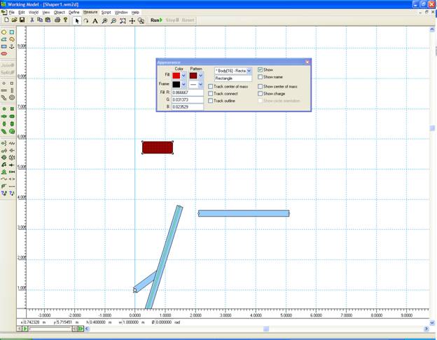
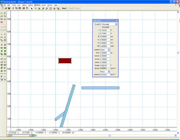
Right click on link 6.
Choose Properties
Change material to Plastic
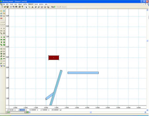
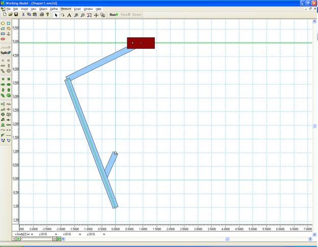
Add a joint to center of this
rectangle.
Move link 6 to y=5 using the lower
left corner window
Join links 4 and 5
Choose Keyed Slot Joint. Click on
link 6. This will ensure that link 6 remains horizontal

Connect links 5 and 6 using Join
If you click on RUN, you will get
this message.
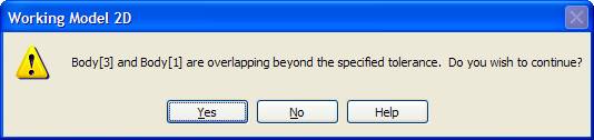
Click No.
Select all links
Object
Do
not Collide
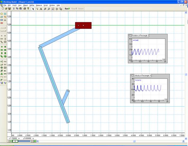
If you click on RUN, the mechanism
will start moving.
Click RESET to return to the original
configurations.
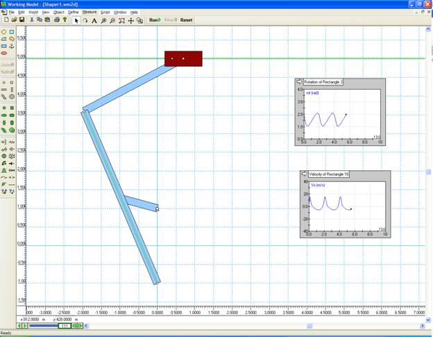
To check the angle of the link 4,
select the link, click on:
|
Measure |
|
|
|
|
Position |
|
|
|
|
Rotation Graph |
To check the velocity of the output
link, select the link, click on:
|
Measure |
|
|
|
|
Velocity |
|
|
|
|
X Graph |
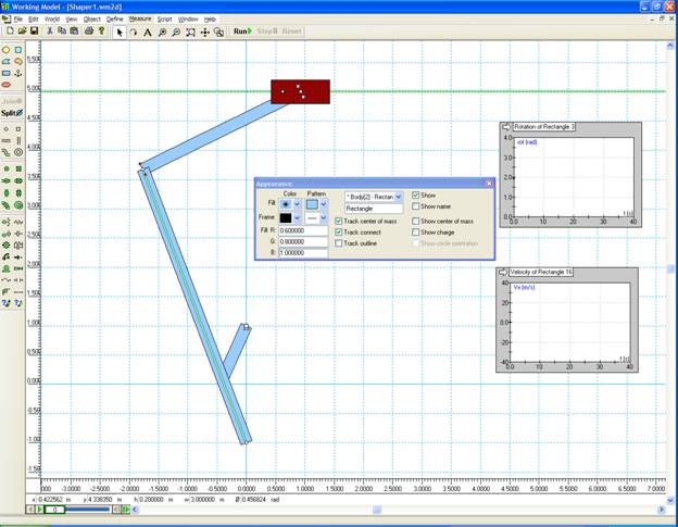
Two new windows appear that trace
the parameters you requested when you run the model.
You can view more than one frame by right clicking on link 5
Appearance,
Track center of mass
Track connect.
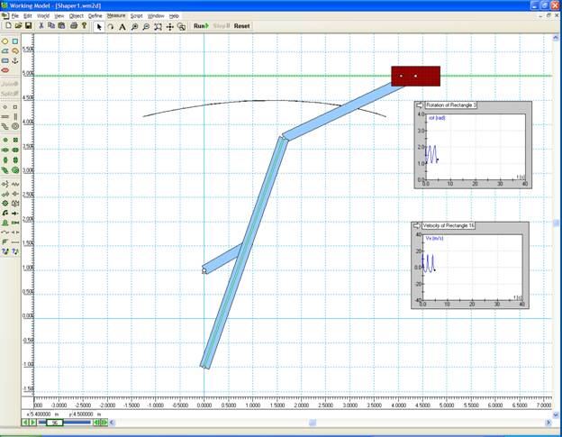
Click on Run again
The simulation video was recorded using:
File
Export
Video for Windows.