Objective: Construct a four-bar linkage with the
following links 1 (crank), 2 (coupler), 3 (output), and 2.5 (fixed links) units
Housekeeping Preparations:
|
View |
|
|
|
|
Workspace |
|
|
|
|
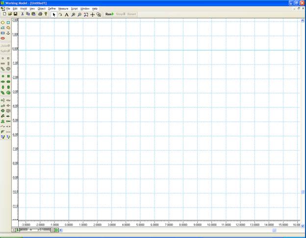
Ruler |
|
|
|
Grid Lines |
|
|
|
X,Y Axes |
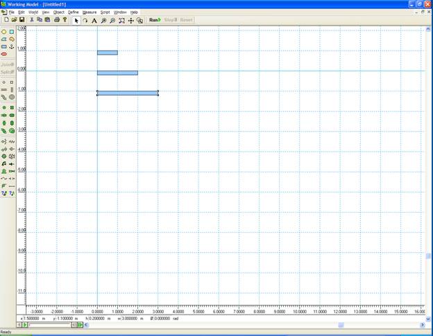
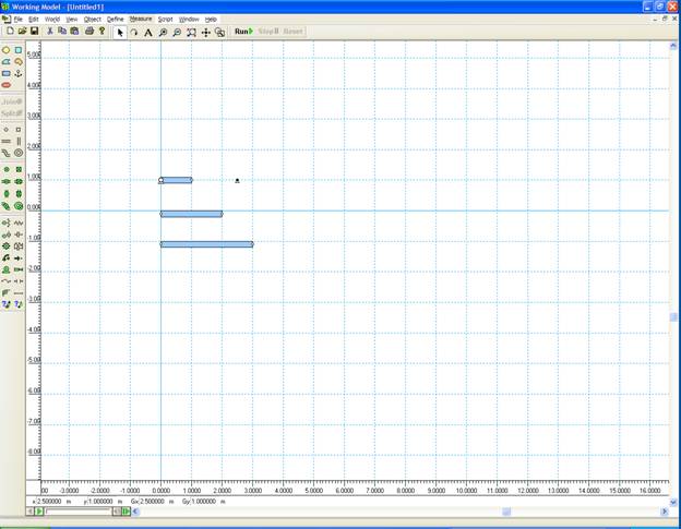
Click on the Rectangle Icon
Create three rectangle of width 0.2
and lengths of 1, 2, and 3 respectively. Dimensions will be shown in the lower
edge of the screen.
Click on the
MOTOR Icon. Place it at the center of the right edge of the shortest
rectangle.
Double click on it to open
properties. Change velocity to 3.1415927 rad/s.
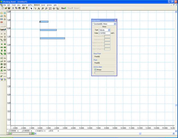
Close the box. Base point is defined
as Point 4.
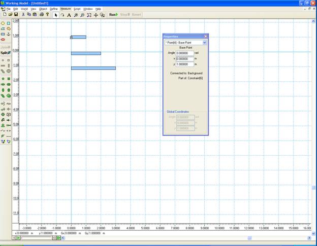
Windows
Properties
Select Point 4.
Change Coordinates to (0,1). The link and the motor
may move slightly.
If you click RUN button the motor
and the attached link will rotate while the two other links will fall down.
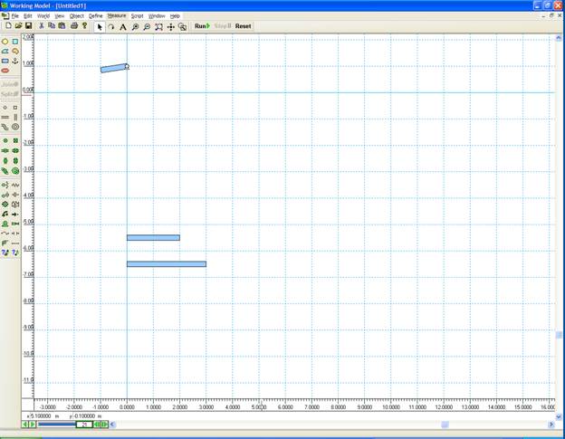
Click Reset. Everything will go back
as before.
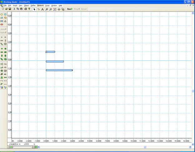
Use POINT element
(hinge joint) to add revolute joints
near the middle of the ends of each link, except where the motor is attached. These points are where the joints will be
located.
Double click on each point to adjust
its coordinates if needed. You can use
either global coordinates or local coordinates (with respect to the center of
the object).
Add a POINT at (2.5,1). This will be the other fixed joint.
Click on a joint. Press shift and
click on the corresponding point on the other link.
Connect points using JOIN. You may have to move the joints close to
each other to assemble the mechanism.
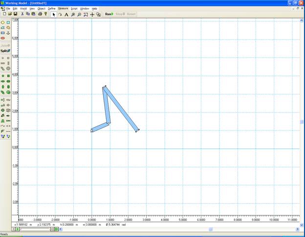
If you click on RUN, the mechanism will
start moving. It may stop after a warning screen shows.
The default in Working Model is all
bodies collide. To avoid this:
Shift + select the three links
Object
Do
not Collide
Click RESET to return to the
original configurations.
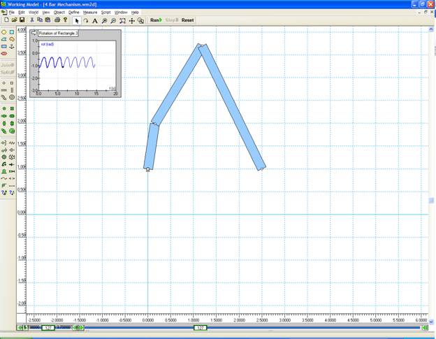
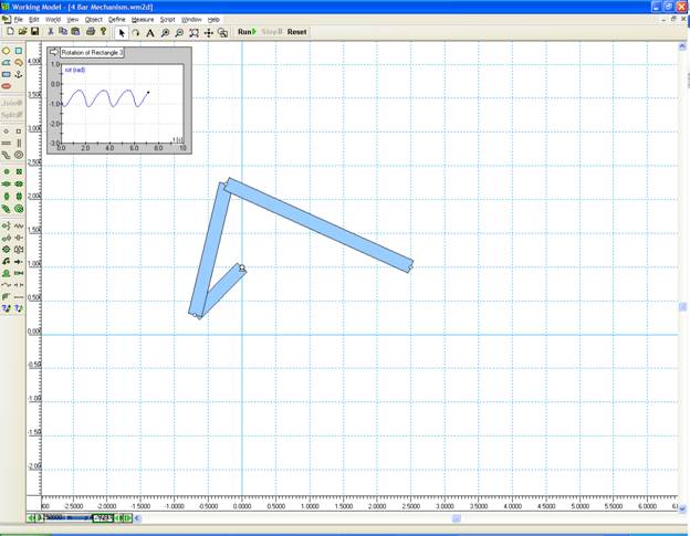
To check the oscillation of the
output link, select the link, click on:
|
Measure |
|
|
|
|
Position |
|
|
|
|
Rotation Graph |
A new window appears that traces the
oscillation of this link when you run the model.
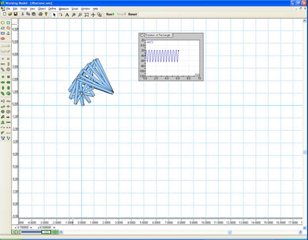
You can view more than one frame by selecting
Windows
Appearance
Track outline.
To create a video of the simulation,
File
Export
Export Type: Video for Windows (*.avi)