Animation of 4-Bar Linkage Using SolidWorks
Objective: Construct a four-bar linkage with the
following links 1 (crank), 2 (coupler), 3 (output), and 2.5 (fixed links) units
Units: Inches
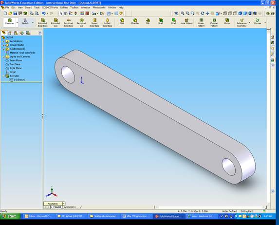
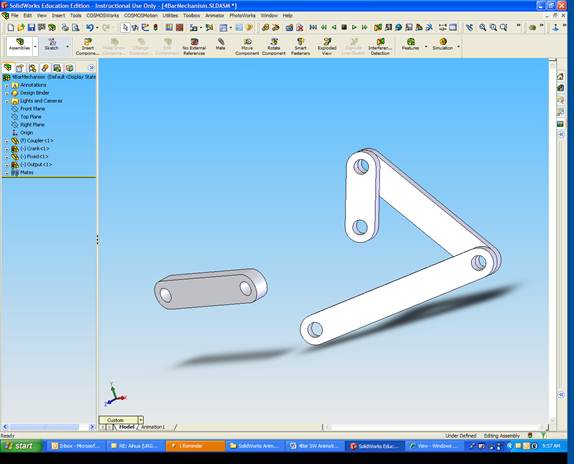
Create
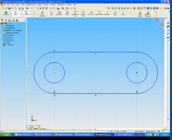
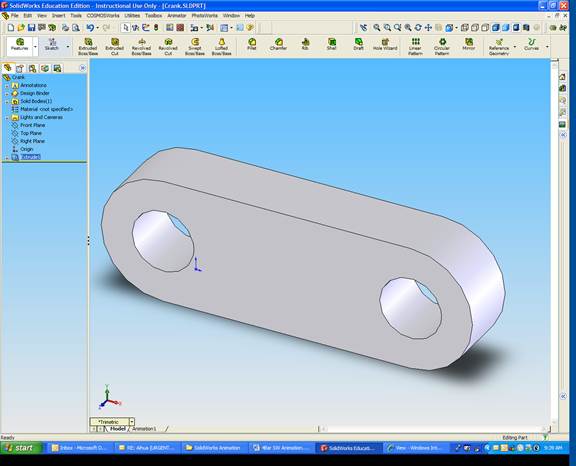
Crank
Create sketch
Extrude sketch
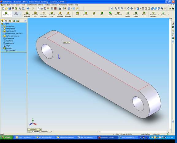
Create Coupler
Create Output
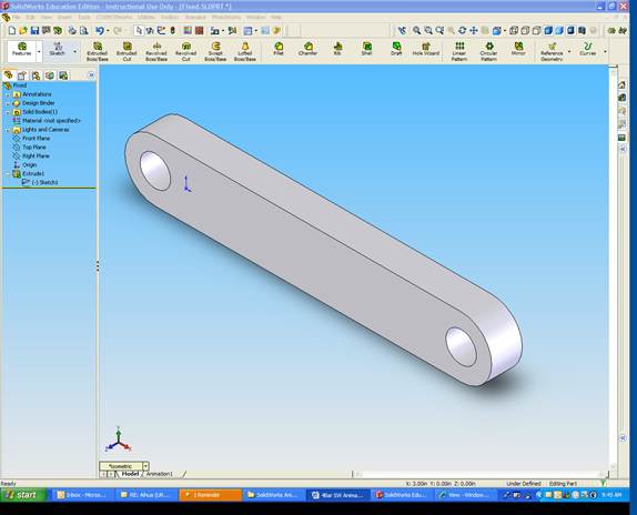
Create Fixed Link
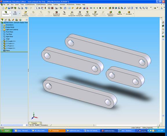
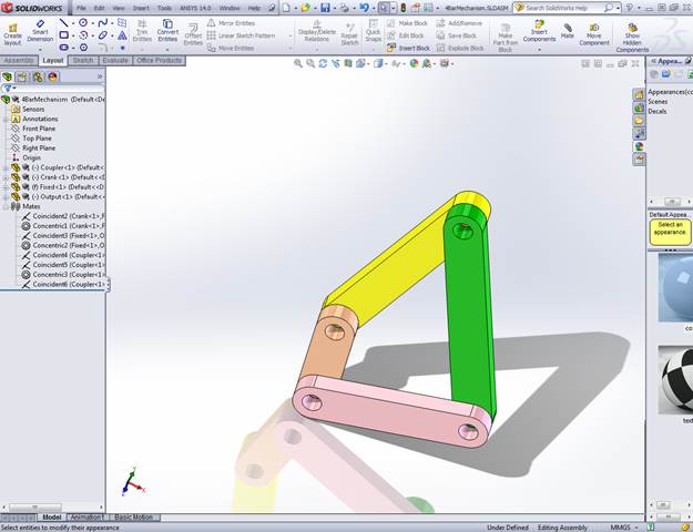
Assemble Mechanism
Match crank and fixed faces
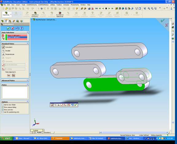
Match holes on crank and fixed
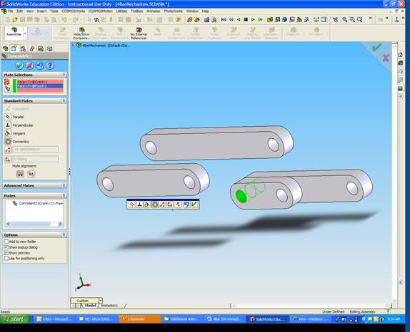
Repeat for Output and Fixed links
Connect Coupler Link to Input and Output Links
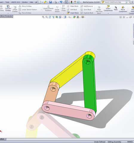
Assign each link a different color for ease of viewing
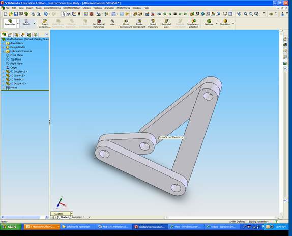
Right Click on Fixed Link
Select Fix
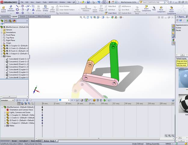
Click Insert
Select New Motion Study.
A new window appears at the bottom of the screen
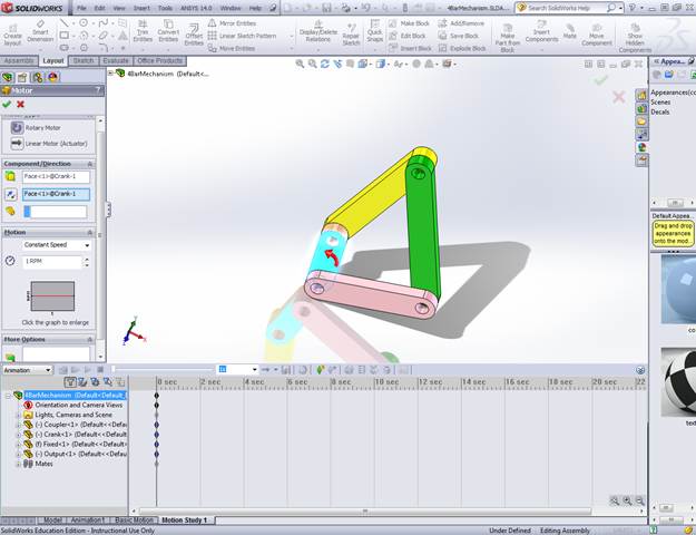
Pick Motor
Click the front surface of the crank
In Motion, Type 1 rpm
Click OK
Drag the simulation vertical line to 60 seconds (to view full cycle)
Click Play (green) button
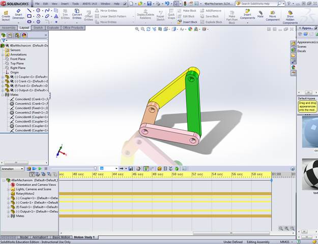
The mechanism will rotate
You can replay the motion by selecting Play from Start
To output as AVI file, select Save Animation
Click here, to view the animation.
You can do more sophisticated analysis using Solidworks Motion
If it is not installed, you need to do the following:
Select Motion Analysis for the pull down menu
Click
Results and Plots
Choose
Displacement/velocity/acceleration
Choose Angular Velocity
Choose outside surface of the rocker
link
Choose the output link
Click
OK
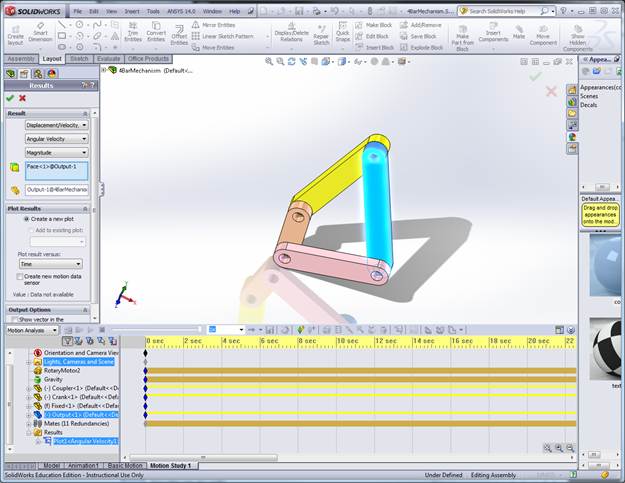
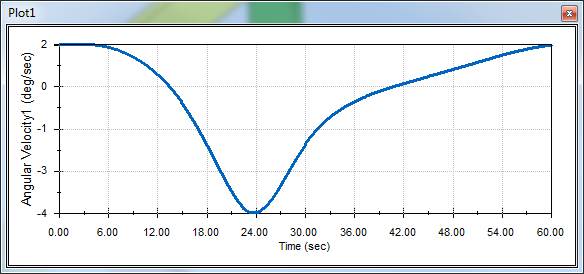
Result:
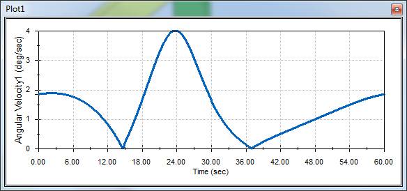
If
z-component is chosen
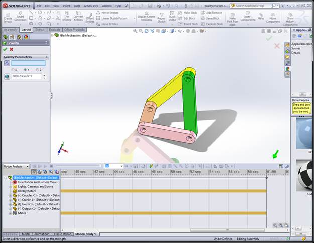
Calculate
the torque needed to aceive this motion in presence of a gravity field
Select Gravity
Choose Y-direction
Click OK
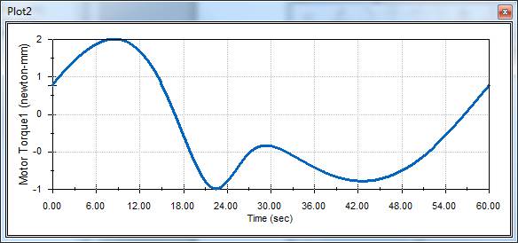
Click Results and Plots
Choose Forces
Choose Motor Torque
Choose Z Component
Choose Rotary Motor
Choose the crank link
Click
OK
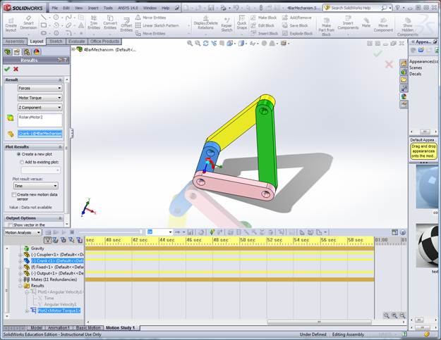
Result: